This set of Machine Design Multiple Choice Questions & Answers (MCQs) focuses on “Coefficients of Flywheel & Solid Disk Flywheel”.
1. Calculate the coefficient of fluctuation of speed if maximum speed is 2500rpm and minimum speed is 1800rpm.
a) 1.44
b) 1.33
c) 0.33
d) 0.44
View Answer
Explanation: C=2[(Max-Min)/(Max+Min)].
2. Calculate the coefficient of steadiness if maximum speed of flywheel is 2500rpm and minimum speed is 1800rpm.
a) 3.03
b) 0.33
c) 0.44
d) 3.99
View Answer
Explanation: C=1.Coeffecient of fluctuation of speed.
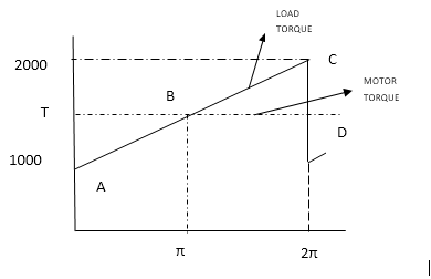
3. Calculate the mean torque T supplied by motor (Torque vs. theta graph of a flywheel is shown below).

a) 3000N-m
b) 1500N-m
c) 2000N-m
d) 2500N-m
View Answer
Explanation: T[1000+2000/2]x2π/2π.
4. The point where angular velocity is maximum is?

a) A
b) B
c) C
d) D
View Answer
Explanation: The flywheel is decelerated in the portion BC and hence rpm is least at C.
5. The point where velocity of flywheel is maximum is

a) A
b) B
c) C
d) D
View Answer
Explanation: Flywheel is accelerated in the portion AB and hence velocity is maximum at B.
6. Calculate the energy output from flywheel.

a) 500π
b) 150π
c) 200π
d) 250π
View Answer
Explanation: U=Area of ΔBCD as max and min velocities are at B and C.
7. Torque vs. theta graph of a flywheel is shown. Coefficient of fluctuation of speed is 0.2 and the mean angular velocity of the machine is 25 rad/s. Thickness of flywheel is 20mm and density of steel used is 7700kg/mᵌ. Calculate the outer radius of the flywheel.

a) 402mm
b) 202mm
c) 540mm
d) 468mm
View Answer
Explanation: I=U/ω²C and I=πptR⁴/2.
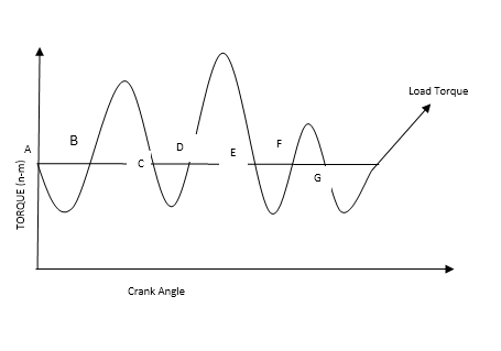
8. The turning moment diagram of a multi cylinder engine is shown below. The intercepted areas between torque developed by the engine and the mean resisting torque of the machine taken in order from one end are -300,+850 -500, + 900, -550, + 430 and -700 mm². Calculate the energy at point B if energy assumed at point A is U.

a) U
b) U-300
c) U+300
d) U-150
View Answer
Explanation: Simple addition of energy.
9. The turning moment diagram of a multi cylinder engine is shown below. The intercepted areas between torque developed by the engine and the mean resisting torque of the machine taken in order from one end are -300,+850 -500, + 900, -550, + 430 and -700 mm². Calculate the energy at point C if energy at point A is U.

a) U-550
b) None of the listed
c) U+550
d) U+550
View Answer
Explanation: E=U-300+ 850.
10. The turning moment diagram of a multi cylinder engine is shown below. The intercepted areas between torque developed by the engine and the mean resisting torque of the machine taken in order from one end are -300,+850 -500, + 900, -550, + 430 and -700 mm². Calculate the energy at point F if energy at A is u.

a) U+340
b) U+260
c) U+400
d) Can’t be determined
View Answer
Explanation: E=U-300+850-500+900-550.
11. The turning moment diagram of a multi cylinder engine is shown below. The intercepted areas between torque developed by the engine and the mean resisting torque of the machine taken in order from one end are -300,+850 -500, + 900, -550, + 430 and -700 mm². Calculate the maximum energy.

a) U+1000
b) U+950
c) U+630
d) U+600
View Answer
Explanation: Maximum energy is at E. E=U-300+850-500+900.
12. The turning moment diagram of a multi cylinder engine is shown below. The intercepted areas between torque developed by the engine and the mean resisting torque of the machine taken in order from one end are -300,+850 -500, + 900, -550, + 430 and -700 mm². Calculate the point of minimum energy.

a) U+480
b) U+650
c) U-300
d) U-450
View Answer
Explanation: Minimum energy is at B. E=U-300.
13. The turning moment diagram of a multi cylinder engine is shown below. The intercepted areas between torque developed by the engine and the mean resisting torque of the machine taken in order from one end are -300,+850 -500, + 900, -550, + 430 and -700 mm². Calculate the net energy output from the flywheel.

a) 1300mm²
b) 1400mm²
c) 1250mm²
d) 1500mm²
View Answer
Explanation: Maximum energy at E[U+950] and minimum at B[U-300]. Thus net energy=[U+950]-[U-300].
14. Feather key can be used to prevent axial motion between two elements.
a) True
b) False
View Answer
Explanation: All types of key but feather key can be used to prevent axial motion between two machine elements.
15. Keyed joints never lead to stress concentration on shafts.
a) True
b) False
View Answer
Explanation: Keyway results in stress concentration in the shaft and makes the part weak.
Sanfoundry Global Education & Learning Series – Machine Design.
To practice all areas of Machine Design, here is complete set of 1000+ Multiple Choice Questions and Answers.
If you find a mistake in question / option / answer, kindly take a screenshot and email to [email protected]
- Check Mechanical Engineering Books
- Check Machine Design Books
- Practice Mechanical Engineering MCQs
- Apply for Mechanical Engineering Internship
- Check Metallurgical Engineering Books

