This set of Refrigeration Multiple Choice Questions & Answers (MCQs) focuses on “Multiple Evaporators and Compressor System – 1”.
1. Multiple evaporator system is used to maintain different temperatures at different points.
a) False
b) True
View Answer
Explanation: Multiple evaporator system is used to maintain different temperatures at a different point as per the specific requirements. For example, fresh fruits and fresh vegetables need to be stored in optimum temperatures and frozen products, dairy products to be stored at different optimum temperatures; for such cases, multiple evaporator system is beneficial.
2. Vegetables, Fruits, Frozen products can be maintained at the same temperatures and humidity.
a) False
b) True
View Answer
Explanation: Multiple evaporator system is used to maintain different temperatures at a different point as per the specific requirements. For example, fresh fruits and fresh vegetables need to be stored in optimum temperatures and frozen products, dairy products to be stored at different optimum temperatures; for such cases, multiple evaporator system is beneficial. Hence, these different products cannot be maintained at the same temperatures and humidity; otherwise, it will lead to ruining of the products.
3. Which of the following system is used for maintaining at the same temperatures when food products kept in different compartments?
a) Evaporator at the same temperature with a single compressor
b) Evaporator at the same temperature with multiple compressors
c) Evaporator at different temperature with a single compressor
d) Evaporator at different temperature with multiple compressors
View Answer
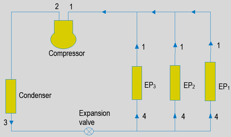
Explanation: For the given case, Multiple evaporators at the same temperatures with a single compressor and expansion valve is used. Though food products are kept in different compartments, the temperatures to be maintained is the same. Hence, this arrangement gives the effective output.
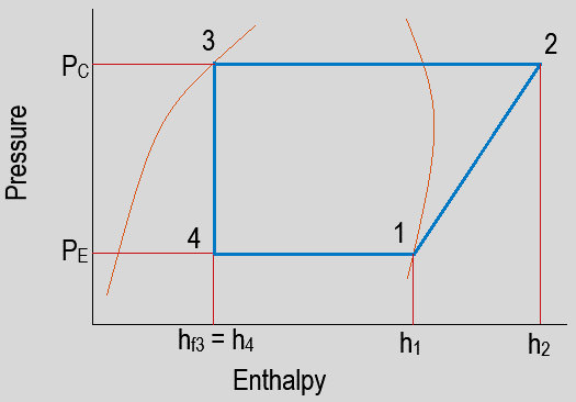
4. What do PC and PE represent?
a) Evaporator and expansion pressure
b) Compression and expansion pressure
c) Condenser and evaporator pressure
d) Intercooling pressure
View Answer
Explanation: PC is for condenser pressure. The pressure at which latent heat is rejected from the refrigerant and converting vapor form to liquid form. PE is for evaporator pressure. The pressure at which latent heat of vaporization is absorbed from the medium and phase change from liquid to vapor is carried out. Attaining and maintaining these pressures is essential for the smooth operation of the cycle.
5. What does process 1-2 represent?
a) Evaporation
b) Compression
c) Condensation
d) Expansion
View Answer
Explanation: Process 1-2 represent compression. This type of compression is isentropic compression, which is carried out in the compressor, and pressure is enhanced from PE to PC.
6. What does process 2-3 represent?
a) Evaporation
b) Compression
c) Condensation
d) Expansion
View Answer
Explanation: Process 2-3 represent condensation. This process results in the phase change of refrigerant from superheated vapor to liquid form at the condenser pressure.
7. What does process 2-3 represent?
a) Evaporation
b) Compression
c) Condensation
d) Expansion
View Answer
Explanation: Process 3-4 represent expansion. This process results in expanding the liquid refrigerant from condenser pressure to evaporative pressure.
8. What does process 4-1 represent?
a) Evaporation
b) Compression
c) Condensation
d) Expansion
View Answer
Explanation: Process 4-1 represent evaporation. This process results in a phase change of refrigerant from liquid to vapor form at the evaporator pressure. Multiple evaporators at the same temperatures are used. Evaporation process gives the refrigeration effect.
9. What is the total mass of refrigerant flowing through the compressor if the masses flowing through each evaporator are m1, m2, and m3?
a) m1 – m2 – m3
b) m1 + m2 – m3
c) m1 – m2 + m3
d) m1 + m2 + m3
View Answer
Explanation: m1 is the mass flowing through EP1 i.e. first evaporator, which is given by 210 Q1 / h1 – h4
m2 is the mass flowing through EP2 i.e., the second evaporator, which is given by 210 Q2 / h1 – h4
m3 is the mass flowing through EP3 i.e., the third evaporator, which is given by 210 Q3 / h1 – h4
As the evaporators are connected in such a way that masses get converged and then enter into the compressor.
So, mass flowing through the compressor will be the summation of masses flowing through each evaporator.
Mass of refrigerant flowing through compressor, m = m1 + m2 + m3.
10. What is the value of work done in the following arrangement?
a) m1 – m2 – m3 (h2 – h1)
b) m1 + m2 + m3 (h2 – h1)
c) m1 + m2 – m3 (h2 – h1)
d) m1 + m2 + m3 (h4 – h1)
View Answer
Explanation: m1 is the mass flowing through EP1 i.e. first evaporator, which is given by 210 Q1 / h1 – h4
m2 is the mass flowing through EP2 i.e., the second evaporator, which is given by 210 Q2 / h1 – h4
m3 is the mass flowing through EP3 i.e., the third evaporator, which is given by 210 Q3 / h1 – h4
As the evaporators are connected in such a way that masses get converged and then enter into the compressor.
So, mass flowing through the compressor will be the summation of masses flowing through each evaporator.
Mass of refrigerant flowing through compressor, m = m1 + m2 + m3
The enthalpy change across the compressor is h1 and h2.
Work done = mass of refrigerant flowing through the compressor x enthalpy change across the compressor.
= m1 + m2 + m3 (h2 – h1).
11. What is the value of the refrigeration effect in the following arrangement?
a) m1 – m2 – m3 (h2 – h1)
b) m1 + m2 + m3 (h4 – h1)
c) m1 + m2 + m3 (h1 – h4)
d) m1 + m2 – m3 (h4 – h1)
View Answer
Explanation: m1 is the mass flowing through EP1 i.e. first evaporator, which is given by 210 Q1 / h1 – h4
m2 is the mass flowing through EP2 i.e., the second evaporator, which is given by 210 Q2 / h1 – h4
m3 is the mass flowing through EP3 i.e., the third evaporator, which is given by 210 Q3 / h1 – h4
As the evaporators are connected in such a way that masses get converged and then enter into the compressor.
Total mass of refrigerant flowing through the evaporator, m = m1 + m2 + m3
The enthalpy change across the evaporator is h1 and h4.
Total Refrigeration effect = Total mass of refrigerant flowing through the evaporator x enthalpy change across the evaporator
= m1 + m2+ m3 (h1 – h4).
12. What is the value of C.O.P. in the following arrangement?
a) (h1 – h4) / (h2 – h1)
b) (h1 – h4) / (h4 – h1)
c) (h1 – h2) / (h4 – h1)
d) (h2 – h3) / (h2 – h1)
View Answer
Explanation: m1 is the mass flowing through EP1 i.e. first evaporator, which is given by 210 Q1 / h1 – h4
m2 is the mass flowing through EP2 i.e., the second evaporator, which is given by 210 Q2 / h1 – h4
m3 is the mass flowing through EP3 i.e., the third evaporator, which is given by 210 Q3 / h1 – h4
As the evaporators are connected in such a way that masses get converged and then enter into the compressor.
Total mass of refrigerant flowing through the evaporator, m = m1 + m2 + m3
The enthalpy change across the evaporator is h1 and h4.
Total Refrigeration effect = Total mass of refrigerant flowing through the evaporator x enthalpy change across the evaporator
= m1 + m2 + m3 (h1 – h4)
So, mass flowing through the compressor will be the summation of masses flowing through each evaporator.
Mass of refrigerant flowing through compressor, m = m1 + m2 + m3
The enthalpy change across the compressor is h1 and h2.
Work done = mass of refrigerant flowing through the compressor x enthalpy change across the compressor.
= m1 + m2 + m3 (h2 – h1)
So, C.O.P. = Total Refrigeration effect / Work done
= (m1 + m2 + m3) (h1 – h4) / (m1 + m2 + m3) (h2 – h1)
= (h1 – h4) / (h2 – h1).
13. What is the value of C.O.P. in the following arrangement?
If the values of enthalpy at point 1, 2 and 3 are 184, 210 and 75 kJ/kg and masses are m1 = 13 kg/min, m2 = 15 kg/min and m3 = 28.085 kg/min
a) 6.23
b) 1.88
c) 4.19
d) 0.2386
View Answer
Explanation: Given: h1 = 184 kJ/kg, h2 = 210 kJ/kg and h3 = h4 = 75 kJ/kg
Though masses are given but for work done and refrigeration effect, summation is same. So, it is a redundant data.
C.O.P. = R.E. / Work done
= (h1 – h4) / (h2 – h1)
= (184 – 75) / (210 – 184)
= 109 / 26
= 4.19.
14. What is the value of mass flowing through the compressor in the following arrangement?
If the values of enthalpy at point 1, 2 and 3 are 184, 210 and 84 kJ/kg and refrigeration capacities are 10, 15 and 20 TR respectively.
a) 94.5 kg/min
b) 32.6 kg/min
c) 49.5 kg/s
d) 94.5 kg/s
View Answer
Explanation: Given: h1 = 184 kJ/kg, h2 = 210 kJ/kg and h3 = h4 = 84 kJ/kg
Q1 = 10 TR, Q2 = 15 TR and Q3 = 20 TR
As we know, m = 210 Q / (h1 – h4)
m1 is the mass flowing through EP1 i.e. first evaporator, which is given by 210 Q1 / h1 – h4,
m1 = 210 x 10 / (184 – 84) = 2100 / 100 = 21 kg/min
m2 is the mass flowing through EP2 i.e. second evaporator, which is given by 210 Q2 / h1 – h4,
m2 = 210 x 15 / (184 – 84) = 3150 / 100 = 31.5 kg/min
m3 is the mass flowing through EP3 i.e., the third evaporator, which is given by 210 Q3 / h1 – h4,
m3 = 210 x 20 / (184 – 84) = 4200 / 100 = 42 kg/min
So, mass flowing through the compressor will be the summation of masses flowing through each evaporator.
Mass of refrigerant flowing through compressor, m = m1 + m2 + m3
m = 21 + 31.5 + 42 = 94.5 kg/min.
15. What is the value of Refrigeration effect in the following arrangement?
If the values of enthalpy at point 1, 2 and 3 are 170, 240 and 107 kJ/kg and masses are m1 = 13 kg/min, m2 = 15 kg/min and m3 = 19 kg/min
a) 3000 kJ/min
b) 2961 kW
c) 2861 kW
d) 2961 kJ/min
View Answer
Explanation: Given: h1 = 170 kJ/kg, h2 = 240 kJ/kg and h3 = h4 = 107 kJ/kg
Total mass of refrigerant flowing through the evaporator, m = m1 + m2 + m3
Total mass flowing through the evaporator = m1 + m2 + m3 = 13 + 15 + 19 = 47 kg/min
The enthalpy change across the evaporator is h1 and h4.
Total Refrigeration effect = Total mass of refrigerant flowing through the evaporator x enthalpy change across the evaporator
= m1 + m2 + m3 (h1 – h4)
Refrigeration effect = 47 (170 – 107) = 47 x 63 = 2961 kJ/min.
16. What is the power required to run the following arrangement?
If the values of enthalpy at point 1, 2 and 3 are 193, 258 and 56 kJ/kg and masses are m1 = 11 kg/min, m2 = 21 kg/min and m3 = 28 kg/min.
a) 65 kJ/min
b) 65 kW
c) 3900 kW
d) 4000 kJ/min
View Answer
Explanation: Given: h1 = 193 kJ/kg, h2 = 258 kJ/kg and h3 = h4 = 56 kJ/kg
As, the evaporators are connected in such a way that masses get converged and then enter into the compressor.
Total mass of refrigerant flowing through the evaporator, m = m1 + m2 + m3
Total mass flowing through the compressor = m1 + m2 + m3 = 11 + 21 + 28 = 60 kg/min
The enthalpy change across the compressor is h1 and h2.
Work done = Total mass of refrigerant flowing through the compressor x enthalpy change across the compressor.
= m1 + m2 + m3 (h2 – h1)
Work done = 60 (258 – 193) = 60 x 65 = 3900 kJ/min
Power = Work done / 60 = 3900 / 60 = 65 kW.
Sanfoundry Global Education & Learning Series – Refrigeration & Air Conditioning.
To practice all areas of Refrigeration & Air Conditioning, here is complete set of 1000+ Multiple Choice Questions and Answers.
If you find a mistake in question / option / answer, kindly take a screenshot and email to [email protected]
- Apply for Mechanical Engineering Internship
- Check Mechanical Engineering Books
- Practice Mechanical Engineering MCQs
- Check Refrigeration & Air Conditioning Books
