This set of MATLAB Multiple Choice Questions & Answers (MCQs) focuses on “Modeling – 1”.
1. What has been modelled in the following Simulink screenshot?
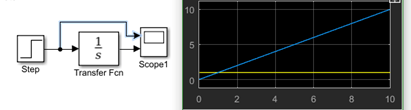
a) The step response of the unit step signal with a step time=0
b) The step response of the ramp signal with a step time=4
c) The ramp response of the step signal with a ramp slope=1
d) The step response of the unit step signal with a step time=2
View Answer
Explanation: Since the step function is given as an input to the system whose transfer function is s, the above screenshot shows the modelling of a system whose impulse response is a step function while the input is also a step function. The graph suggests that step time is 0.
2. The system, that has been modelled in the following Simulink screenshot has ___ initial conditions.
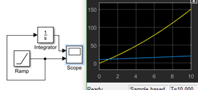
a) 0
b) Some
c) Impossible
d) Cannot be determined
View Answer
Explanation: We note that the ramp function does not start from 0 at t=0. This implies that it has some initial conditions.
3. Digital systems ______ in Simulink.
a) Can be implemented
b) Cannot be implemented
c) Only ADC’s
d) Only DAC’s
View Answer
Explanation: Logic systems and bitwise operator section under Simulink provides the user with a multitude of operators for digital system. MATLAB also has HDL doe verifier.
4. The no. of logical operations present in the logical operator block is _________
a) 6
b) 7
c) 5
d) 3
View Answer
Explanation: The logical operations present are AND, NOT, OR, NAND, NOR, XOR and XNOR. Hence, the correct option is 7.
5. The arrows connecting each block with another are ____
a) Flexible as in they don’t become permanent when once placed
b) Rigid as in their direction cannot be changed
c) Don’t pop up in the screen
d) Absent
View Answer
Explanation: By clicking the head of the arrow, we can drag it and change it’s direction. Also we change the alignment of the body by keeping the cursor pressed on the arrow body, while moving that part of the body. It does show on the screen, i.e. it’s head and it’s tail.
6. The output at scope 1 is?
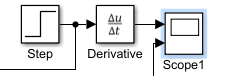
a) 0
b) Impulse function
c) Ramp function
d) Step function
View Answer
Explanation: The derivative of the step function is 0. This is because the step function has a constant amplitude.
7. What have we modelled here?
a) A capacitor which is blocking DC
b) An inductor which is blocking AC
c) A resistor whose resistance changes with temperature
d) A capacitor which is being charged
View Answer
Explanation: The output of the derivative block will be 0. Hence this system shows a model of the event described in capacitor which is blocking DC. Note that to model option inductor which is blocking AC, we need an integrator which takes a high frequency sinusoid.
8. What can be the possible limitation of this block?
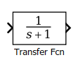
a) No. of zeros never equal to no. of poles not allowed
b) No. of zeros lesser than no. of poles not allowed
c) No. of zeros greater than no. of poles not allowed
d) No. of zeros equal to no. of poles not allowed
View Answer
Explanation: The system having more zeros than poles is extremely unstable and not realizable. Hence, this is the only possible limitation of the given block.
9. The limits of the graph obtained from the scope can be changed from the ________
a) Configuration properties
b) Style option
c) Layout option
d) Stepping option
View Answer
Explanation: In the window, which contains the graph obtained from the scope block- there is the option of Configuration Properties in the View option. We can modify the limits of both axis from that segment. The layout and style options don’t contain the axes.
10. For this block, the early voltage is always infinite.

a) Yes
b) No
c) Not always
d) Cannot be determined
View Answer
Explanation: The Early voltage can be specified amongst the parameters of the NPN B.J.T. It can also be put to Infinite for the sake of calculations- though it never happens in reality.
Sanfoundry Global Education & Learning Series – MATLAB.
To practice all areas of MATLAB, here is complete set of 1000+ Multiple Choice Questions and Answers.
If you find a mistake in question / option / answer, kindly take a screenshot and email to [email protected]
