This set of Machine Dynamics Multiple Choice Questions & Answers (MCQs) focuses on “Bennett’s Construction”.
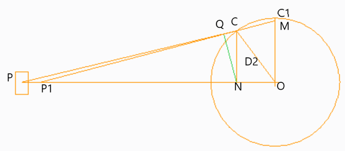
1. If OC is the crank and PC is the connecting rod rotating in clockwise direction in the figure given below, then triangle OCM is known as _________
a) Klein’s velocity diagram
b) Klein’s acceleration diagram
c) Bennett’ velocity diagram
d) Bennett’ acceleration diagram
View Answer
Explanation: Since the crank is rotating in the clockwise direction, then the velocity of C will be perpendicular to OC and it’s value is given by w2.OC, hence triangle OCM forms a velocity polygon.
2. Bennett’ construction is used when the motion of the crank is linear cycloidal.
a) True
b) False
View Answer
Explanation: Bennett’ construction is used when the crank is undergoing a motion which has uniform angular velocity.
3. From figure, acceleration of P with respect to C is given by_________
a) ω2.CN
b) ω2.QN
c) ω2.PC
d) ω2.OM
View Answer
Explanation: Total acceleration is the vector sum of radial and tangential components radial component is given by ω2.CQ and tangential component is given by ω2.QN.
4. Acceleration of any point D on the connecting rod is given by ________
a) ω2.OD1
b) ω2.OD2
c) ω2.OD
d) ω2.PD
View Answer
Explanation: Acceleration at D is the vector sum of radial acceleration and tangential acceleration components. Hence the net acceleration is ω2.OD2
5. In which of the following cases Bennett’s construction can be used?
a) Crank has a uniform angular velocity
b) Crank has a uniform angular acceleration
c) Lever has a uniform angular acceleration
d) When the motion is SHM
View Answer
Explanation: Bennett’s construction can be used in both the cases, i.e when the crack has both uniform and non uniform angular velocity.
6. From figure, what is the velocity of P with respect to C?
a) ω × OC
b) ω × OM
c) ω × CM
d) ω × QN
View Answer
Explanation: In the figure, the triangle OCM is known as the velocity diagram, referring to that will provide us the velocity of point P with respect to C. Velocity if C wrt to O is ω × OC and ω × OM is velocity of P wrt to O.
7. From figure, what is the absolute velocity of P, i.e velocity of P with respect to the stationary point O?
a) ω × OC
b) ω × OM
c) ω × CM
d) ω × QN
View Answer
Explanation: In the figure, the triangle OCM is known as the velocity diagram, referring to that will provide us the absolute velocity of point P. Velocity if C wrt to O is ω × OC and ω × OM is velocity of P wrt to O.
8. Bennett’ construction is used to determine graphically the velocity and acceleration of reciprocating parts of an IC engine.
a) True
b) False
View Answer
Explanation: The velocity and acceleration of the reciprocating parts of the steam engine or internal combustion engine are determined by either graphical method or analytical method, Bennett’s construction provides graphical solution for the same.
9. Velocity of any point D on the connecting rod is given by ________
a) ω.OD1
b) ω.OD2
c) ω.OD
d) ω.PD
View Answer
Explanation: Linear velocity is obtained by a product of angular velocity of the crank and the perpendicular distance of the respective point. In this case ω is the angular velocity and OD1 is the perpendicular distance.
Sanfoundry Global Education & Learning Series – Machine Dynamics.
To practice all areas of Machine Dynamics, here is complete set of 1000+ Multiple Choice Questions and Answers.
If you find a mistake in question / option / answer, kindly take a screenshot and email to [email protected]
- Check Dynamics of Machinery Books
- Apply for Aerospace Engineering Internship
- Apply for Mechanical Engineering Internship
- Check Aeronautical Engineering Books
- Practice Mechanical Engineering MCQs
