This set of Machine Dynamics Multiple Choice Questions & Answers (MCQs) focuses on “Velocity and Acceleration Diagrams”.
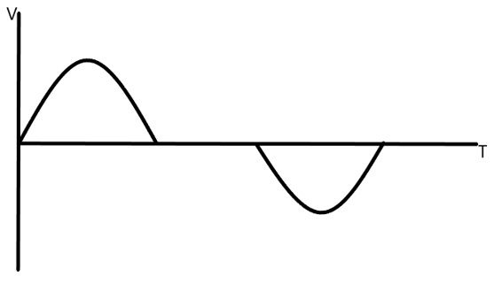
1. The given figure is a velocity time diagram for which of the follower motion?
a) Simple harmonic
b) Uniform acceleration
c) Uniform velocity
d) Uniform retardation
View Answer
Explanation: The given figure is the velocity time diagram of the simple harmonic motion of the follower.
This is similar to the sine curve as the velocity relation is a sine function.
2. For a follower Simple Harmonic Motion having a small period of dwell at the beginning of motion, the jerk is 0.
a) True
b) False
View Answer
Explanation: For a follower undergoing simple harmonic motion, starting off with a small dwell period, when it begins to ascend the acceleration is suddenly increased to a great amount from 0, hence the jerk is also infinite.
3. The given figure is a velocity time diagram for which of the follower motion?

a) Simple harmonic
b) Uniform acceleration
c) Uniform velocity
d) Uniform retardation
View Answer
Explanation: The given figure is the velocity time diagram of the uniform velocity motion of the follower with initial dwell. This is a constant curve as the velocity relation does not change with time.
4. Which of the following motion is not suitable from a practical point of view?
a) Simple harmonic
b) Uniform acceleration
c) Uniform velocity
d) Uniform retardation
View Answer
Explanation: Due to infinite jerks, consequently infinite inertia forces arise as result, this makes the uniform velocity method of follower non-practical.
5. If a follower is undergoing simple harmonic motion, then at what value of angle of ascent the acceleration is maximum?
a) 0
b) 30
c) 45
d) 60
View Answer
Explanation: At 0 degrees, the change in velocity in the motion of follower is maximum under the shm as a result a maximum value of acceleration is obtained at 0 degrees.
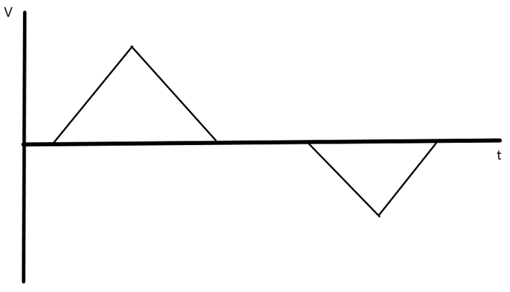
6. The given figure is a velocity time diagram for which of the follower motion?
a) Simple harmonic
b) Uniform acceleration
c) Uniform velocity
d) Uniform acceleration and retardation
View Answer
Explanation: The given figure is the velocity time diagram of the uniform acceleration and retardation motion of the follower with initial dwell. This is a linear curve as the velocity relation changes linearly with time.
7. Which of the following motion is used only up to moderate speeds?
a) Simple harmonic
b) Uniform acceleration
c) Uniform velocity
d) Uniform acceleration and retardation
View Answer
Explanation: It is observed from the plots of uniform acceleration and retardation that there are abrupt changes in the acceleration at the beginning, midway and the end of the follower motion. At midway, an infinite jerk is produced.
8. While constructing cam profile, Kinematic inversion is used.
a) True
b) False
View Answer
Explanation: While cam profile is being constructed, it is assumed that the cam is stationary and the follower moves in the opposite direction to that of cam in reality.
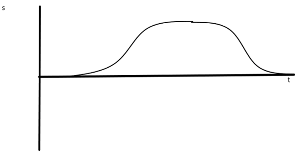
9. From the given figure below, at what value of theta(angle of ascent) the acceleration will be maximum?
a) 0
b) 30
c) 60
d) Constant acceleration
View Answer
Explanation: The given figure is the displacement diagram of the follower undergoing a constant acceleration and retardation motion, thus as a result of that there is a constant value of acceleration and has no maxima and minima.
10. Which of the following motion has the maximum number of infinite jerks in one rotation of the cam shaft?
a) Simple harmonic
b) Uniform acceleration
c) Uniform velocity
d) Uniform acceleration and retardation
View Answer
Explanation: Uniform velocity motion is proved to be useless for practical purposes as there are infinite inertia force results due to many number of infinite jerks between the motion, so from the given options it is observed from the graph that uniform velocity motion has maximum number of jerks in one rotation of the cam shaft.
Sanfoundry Global Education & Learning Series – Machine Dynamics.
To practice all areas of Machine Dynamics, here is complete set of 1000+ Multiple Choice Questions and Answers.
If you find a mistake in question / option / answer, kindly take a screenshot and email to [email protected]
- Practice Mechanical Engineering MCQs
- Apply for Aerospace Engineering Internship
- Check Aeronautical Engineering Books
- Practice Aeronautical Engineering MCQs
- Apply for Mechanical Engineering Internship
