This set of Microelectronics Multiple Choice Questions & Answers (MCQs) focuses on “Characteristics of an Bipolar Amplifiers”.
1. What would be the input impedance of an amplifier if the input is a current?
a) Very High
b) Very Low
c) Highly inductive
d) Highly Capacitive
View Answer
Explanation: The input impedance of the amplifier should be very low. This will prevent the current, being sensed, from getting attenuated at the input.
2. What should be the input impedance of an amplifier, ideally, if the input is a voltage?
a) Infinite
b) 0
c) Highly capacitive
d) Highly inductive
View Answer
Explanation: The input impedance of the amplifier should be ideally infinite. This would prevent any voltage drop before the amplifier senses the input voltage and all the voltage would get amplified.
3. If the output impedance of an amplifier is very high, what should be the nature of output of the amplifier?
a) Voltage
b) Current
c) Power
d) Energy
View Answer
Explanation: The output impedance, if very high, is preferable for amplifiers which generate a current as an output. This allows us to sense the entire current generate at the output of the transistor and increases the accuracy of operation.
4. If the output of the amplifier is a voltage, what should be it’s output impedance?
a) Ideally infinite
b) Ideally zero
c) Highly reactive
d) Cannot be determined
View Answer
Explanation: The output impedance of an amplifier should be ideally zero. This would allow us to sense the entire voltage generated at the output of the amplifier while the amplifier returns the entire generated voltage without any voltage drop.
5. What should be the input impedance of an amplifier if it returns a voltage as an output?
a) Infinite
b) Zero
c) Highly resistive
d) Cannot be determined
View Answer
Explanation: The input impedance of an amplifier is independent of the quantity it returns as an output. Thus, we cannot determine the required input impedance until we know which quantity is to be sensed at the input of the transistor.
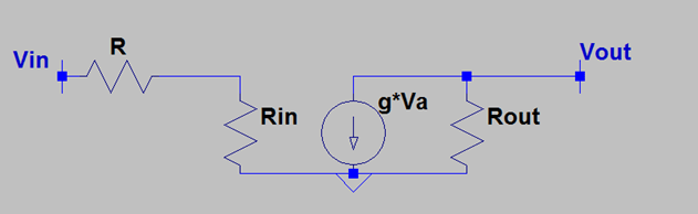
6. In the following figure, Va is the voltage across Rin=1K. If g=20mS, find Rout such that the total voltage gain is 20?

a) 1K
b) 2K
c) 3K
d) 4K
View Answer
Explanation: The output voltage is g * Vin * Rout. Thus the output impedance, Rout, has to be 1K so that the voltage gain becomes 20.
7. What should be the ratio of Rin to R so that the following circuit can behave as a good transconductance amplifier?
a) Very High
b) Very Low
c) Data incomplete
d) 0
View Answer
Explanation: The input voltage suffers a voltage division before entering the amplifier. This leads to the attenuation of the input voltage at the input of the amplifier. To avoid this scenario, the ratio should be very high such that it becomes nearly an open circuit.
8. What should be the ratio of Rin to Rout in the following circuit so that it can behave as a good transconductance amplifier?
a) Very high
b) 0
c) No such relation
d) Cannot be determined
View Answer
Explanation: We are unaware about g. We are unaware about R. In ideal cases, there is no relation suggesting a good ratio of these resistances for making an effective transconductance amplifier We can however say that the input resistance should be very high while the output resistance should be also very high.
9. What is the input impedance of the following amplifier circuit?
a) R
b) Rin
c) R + Rin
d) 8R || Rin
View Answer
Explanation: The resistor R is not a part of the input impedance of the amplifier This is just reflects the output impedance of the preceding stage. The input impedance is simply Rin.
10. How the input resistance gets affected if R4 is increased 10 times?
a) It increases by a factor of 2
b) It increases by a factor of 4
c) It increases by a factor of 7
d) Doesn’t get affected
View Answer
Explanation: The input impedance and the output impedance of the following circuit are sincerely isolated from each other. Any change in the output impedance won’t bring a change in the input impedance of the amplifier.
11. Which kind of amplifier would require a high input and output impedance?
a) Voltage
b) Current
c) Transconductance
d) Trans-resistance
View Answer
Explanation: The transconductance amplifier senses a voltage and requires a very high input impedance. Similarly, it returns a current and hence should offer a very high output impedance to allow the entire generated current to be returned to the output.
12. The ________ amplifier topology would require a low input and output impedance.
a) Current
b) Voltage
c) Transconductance
d) Trans-resistance
View Answer
Explanation: The current amplifier should have a low input and output impedance. This would prevent attenuation of the current sensed at the input and the current generated returned at the output.
13. The power dissipation of an amplifier should be _________
a) Minimum
b) Maximum
c) 0
d) Infinite
View Answer
Explanation: The amplifier should be designed to dissipate the minimum power for both discrete and integrated circuits. This is due to the limited power supply and temperature conditions in the circuit since the high power dissipation can damage the speaker or the circuit board itself.
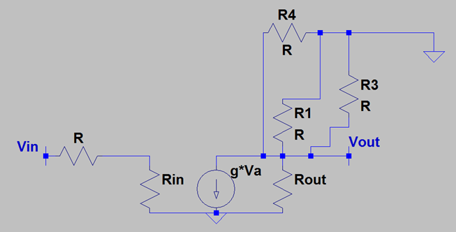
14. What is the output impedance of the following circuit?
a) (Rout || R4) + R1 + R3
b) Rout || R4 || R1 || R3
c) Rout || R4 + R1 || R3
d) (Rout || R4 || R1) + R3
View Answer
Explanation: The output impedance is calculated by thevenising the output port of the circuit. This leads us to the fact that all the resistances are connected from the same node to the ground and the output impedance is Rout || R4 || R1 || R3.
15. In the following circuit, if Rout = R4 = R1 = R3 = R, find the total output impedance if g = 10mS.
a) R/4
b) R/9
c) R/19
d) R/3
View Answer
Explanation: The output impedance of the following circuit is Rout || R4 || R1 || R3. This can be found by thevenising the output port. Hence, the overall output impedance is R/4. Observe that ‘g’ plays no part in the output impedance.
Sanfoundry Global Education & Learning Series – Microelectronics.
To practice all areas of Microelectronics, here is complete set of 1000+ Multiple Choice Questions and Answers.
If you find a mistake in question / option / answer, kindly take a screenshot and email to [email protected]
