This set of Microelectronics Multiple Choice Questions & Answers (MCQs) focuses on “Basics of Frequency Response”.
1. Let x(t)=sint for t=0-T/2 , if the Laplace transform of x(t)=1+exp(-πs)/(s2+1), what is the Laplace transform of -x(t-T/2)?
a) (-exp(-πs)*(1+exp(-πs)/(s2+1))
b) (-exp(-πs)*(1+exp(-πs))
c) (exp(-s)*(1+exp(-πs)/(s2+1))
d) (-exp(-πs)*(1+exp(-πs)/(s2))
View Answer
Explanation: We have scaled the amplitude of x(t) by -1 and we have delayed the signal by an amount of T/2. Hence, X(s) will get multiplied by -exp(-st/2) and the resultant laplace transform is (-exp(-st/2)*(1+exp(-πs)/(s2+1)).
2. If the Laplace transform of x(t) = sin t for t=0-T/2 is 1+exp(-πs)/(s2+1), choose the correct option.
a) The signal is odd
b) The signal is even
c) The signal is periodic
d) The signal is aperiodic
View Answer
Explanation: The given signal is aperiodic. If we want to find the Laplace transform of the signal when x(t) gets repeated with a period T, we need to divide its Laplace transform by 1-exp(-sT) and the resultant will be the Laplace transform of the periodic signal.
3. If the coefficient of E.F.S. of the impulse train is 1/T, T being the period of the signal, what will be the co-efficient for fδ(3t) ?
a) 1/4T
b) 3/T
c) 1/3T
d) 1/T
View Answer
Explanation: The coefficient of EFS do not change if the signal gets scaled by a factor greater than 0. Note that the coefficient if independent of n and even time reversal won’t affect it.
4. Let x(t) = 1 for t=-T/2 to 0 and 0 for 0-T/2. What is the coefficient of x(t-T/2)?
a) (j*2/nπ)*sin2(nπ/3)
b) -(j*2/nπ)*sin(nπ/2)
c) (j*2/nπ)*sin2(nπ/2)
d) -(j*2/nπ)*sin2(nπ/8)
View Answer
Explanation: The coefficient of EFS of x(t) is –(j*2/nπ)*sin2(nπ/2). If we delay the signal by a factor of T/2, we will multiply the co-efficient by a factor of exp(-jnωT/2), ie -1, and the resultant expression is just (j*2/nπ)*sin2(nπ/2).
5. If the signal is a half-wave symmetric signal and it is also and odd signal, the coefficient of EFS will be ____________
a) real and 0 for n=even
b) imaginary and 0 for n=odd
c) real and 0 for n=odd
d) imaginary and 0 for n=odd
View Answer
Explanation: The property of a HWS signal is that the co-efficient of EFS is 0 for n=even. Moreover, since the signal is odd, the coefficients will be imaginary.
6. What is the sum of the coefficients of EFS of cos(ωt)?
a) 0
b) 1
c) 2
d) 3
View Answer
Explanation: We know that cos(ωt)=1/2*(exp(jωt)+exp(-jωt). Equating this expression to the expression of EFS, we find that C1=1/2 & C-1=1/2. Since, these are the only two components of EFS, the sum of the coefficients is 1.
7. The impulse response of a system is given by the __________
a) Inverse Laplace Transform of the Transfer function
b) Inverse Laplace transform of the convolution of input and transfer function
c) Inverse Laplace transform of the input
d) Laplace transform of the convolution of input and transfer function
View Answer
Explanation: The output of a system is given by the convolution of the input and the impulse response of the system. We know that the Laplace transform of the output will be the product of the Laplace transform of the input and the Laplace transform of the impulse response. Hence, the Laplace transform of the impulse response is written as the ratio of Laplace transform of the output and the input, ie the transfer function. If we take the inverse Laplace transform of the transfer function, we obtain the impulse response in time domain.
8. For a causal stable continuous time LTI system, the condition is__________
a) Poles should lie on the left half of the s-plane
b) Poles should lie on the right half of the s-plane
c) Poles should lie on the left half of the s-plane and R.O.C. includes the imaginary axis
d) Poles should lie on the right half of the s-plane and R.O.C. includes the imaginary axis
View Answer
Explanation: The stability of a system is determined from its impulse response. Typically, this implies that the system is represented as a signal and it will have its poles and zeros. Now, for any system to be stable, \(\int_0^∞\) h(t)dt is finite. For a causal system, this can only be finite if the pole lies on the left half of the s-plane while for a non-causal system, this will be finite if the pole lies on the right half of the s-plane. Moreover, the R.O.C. of the Laplace transform of the impulse response will have to include the imaginary axis for σ=0. Thus, for a causal LTI system to be stable, the poles should lie on the left half of the s-plane and R.O.C. should include the imaginary axis.
9. All Causal systems are stable.
a) True
b) False
View Answer
Explanation: The statement is false. Suppose the Impulse response, h(t), of a system is exp(at)u(t). The Laplace transform is 1/s-a. We note that the pole lies on the right half of the s-plane and the R.O.C. includes the right half of a. The R.O.C. does not include the imaginary axis and hence, \(\int_0^∞\) h(t)dt is not finite and the system is unstable even though it is causal.
10. If the impulse response of a system is sinc(t) and the laplace transform of the input is a pulse function ranging from -π to π, what will be the output?
a) sin t
b) cos t
c) sinc(t)
d) Unstable
View Answer
Explanation: The laplace transform of the impulse response is also a pulse ranging from -π to π. We note that the convolution in time domain is multiplication in s domain and hence, the Laplace transform of the output will also be a pulse ranging from -π to π. Finally, we take the inverse laplace transform to get sinc(T).
11. What is the Laplace transform of the following signal? The signal starts from 1 at t=0 and ends at 0 at t=T.
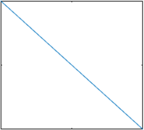
a) 1/s–1/Ts2+exp(sT)/Ts
b) 1/s-1/Ts+exp(-sT)/Ts2
c) 1/s–+exp(-sT)/Ts2
d) 1/s–1/Ts2+exp(-sT)/Ts2
View Answer
Explanation: The above signal is represented as u(t)-r(t)/T+r(t-T)/T where u(t) is the step function and r(t) is the ramp function. Now, we take the Laplace transform for each variable and get 1/s–1/Ts2+exp(-sT)/Ts2.
12. Find the Laplace transform of the following signal. Note that the signal goes to 0 at t=2, the plot i.
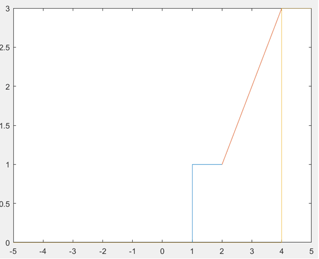
a) exp(-s)/s-2/s2-exp(-4s)/s2-exp(-4s)/s
b) 1/s+exp(-2s)/s-exp(-4s)/s-exp(-4s)/s
c) exp(-s)/s+exp(-2s)/s2-exp(-4s)/s2-exp(-4s)/s
d) exp(-s)/s+exp(-2s)/s-exp(-4s)/s-exp(-4s)/s
View Answer
Explanation: The above signal starts from t=1, as a step function, and increases like a ramp function from t=1 to t=3. At t=3, the signal becomes 0 ie the ramp function first gets converted into a step function and then the step function is subtracted from another step function. This is represented as u(t-1)+r(t-2)-r(t-4)-u(t-4). The Laplace transform is given as exp(-s)/s+exp(-2s)/s2-exp(-4s)/s2-exp(-4s)/s. Note that the slope of the ramp function starting from t=2 is 1 and hence, the ramp function required to make it a step signal at t=4 will also have a slope of 1.
13. The L.T. of the output of a system is 1/s+5–1/s+7. Find the input if the impulse response if exp(-5t)u(t), if the R.O.C. of the input is on the right half of the s-plane.
a) exp(-7t)u(t)
b) -exp(-7t)u(-t)
c) exp(9t)
d) u(t)
View Answer
Explanation: We manipulate the output and write it as 2/(s+5)*(s+7). The output of a system is the product of the Laplace transforms of the input and the impulse response. Since, the L.T. of the impulse response is (1/s+5), the laplace transform of the input is 2/(s+7). Now, the R.O.C. of the input is on the right half of the s-plane and the signal is anti-causal. Thus, the I.L.T. of the input is -exp(-7t)u(-t). If the R.O.C. was in the left half of the s-plane. The input is exp(-7t)u(t).
14. Find the I.L.T. of exp(-45s)/2.
a) δ(t+90)
b) δ(2(t-45))
c) δ(2(t-90))
d) Not unique
View Answer
Explanation: The I.L.T. of the following function is 1/2*δ((t-45)) which is δ(2(t-45)), a property of the impulse function.
15. The Zero-state response of the system is the natural response of the system.
a) True
b) False
View Answer
Explanation: The Zero-state response of the system is the forced response of the system which is due to the input given to the system. The Zero-input response is the natural response of the system & is due to the initial conditions present in the system.
Sanfoundry Global Education & Learning Series – Microelectronics.
To practice all areas of Microelectronics, here is complete set of 1000+ Multiple Choice Questions and Answers.
If you find a mistake in question / option / answer, kindly take a screenshot and email to [email protected]
