This set of High Voltage Engineering Multiple Choice Questions & Answers (MCQs) focuses on “Voltage Dividers”.
1. Potential dividers are usually __________
a) resistive
b) capacitive
c) mixed element type
d) either resistive, capacitive or mixed element type
View Answer
Explanation: The voltage dividers are usually either resistive, capacitive or mixed element type. They are used for high-voltage impulse measurements, high frequency ac measurements, or for fast rising transient voltage measurements.
2. The attenuation factor of the resistance potential divider is (given R1 is greater than R2) __________
a) a=1+(R1/R2)
b) a=R1/R2
c) a=R2/R1
d) a=1+(R2/R1)
View Answer
Explanation: The attenuation factor of the resistance potential divider is a=1+(R1/R2). It is also known as voltage ratio. R1 and R2 are the two resistance connected in series and R1 is greater than R2. R2 is the divider element. It is connected to the oscilloscope through a coaxial cable.
3. The following waveform represents_____
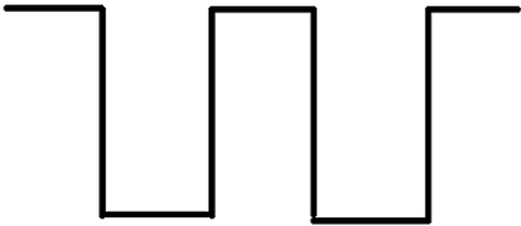
a) overcompensated resistance voltage divider
b) correctly compensated resistance voltage divider
c) undercompensated resistance voltage divider
d) uncompensated resistance voltage divider
View Answer
Explanation: The given waveform represents waveform of correctly compensated resistance voltage divider. Here C1R1=C2RM. C1 is the compensating capacitance and Cm is the oscilloscope input capacitance.
4. The capacitance of the oscilloscope input impedance lies between __________
a) 5-10pF
b) 10-50pF
c) 50-100pF
d) 100-150pF
View Answer
Explanation: The capacitance of the oscilloscope input impedance lies between 10-50pF. The resistance value is usually greater than one mega ohm. The divider is compensated using an additional capacitance in the circuit. Accordingly, various degrees of compensation can be obtained.
5. The resistance potential divider used for high voltage impulse measurement produces __________ along its length.
a) linear current distribution
b) non-linear current distribution
c) linear voltage distribution
d) non-linear voltage distribution
View Answer
Explanation: The resistance potential divider used for high voltage impulse measurement produces non-linear voltage distribution along its length. It can also act like an R-C filter for applied voltages. The introduction of stray capacitances reduces the distortion introduced.
6. The low voltage arm of voltage divider is usually connected to oscillograph.
a) True
b) False
View Answer
Explanation: The low voltage arm of voltage divider is usually connected to peak reading instrument through a delay cable. It can be also connected to a fast recording oscillograph.
7. _________ are best for measurement of fast rising voltages and pulses.
a) resistive potential dividers
b) capacitance potential dividers
c) inductive potential dividers
d) resistive and inductive potential dividers
View Answer
Explanation: Capacitance potential dividers are best for measurement of fast rising voltages and pulses. Here, unlike resistance ratio, capacitance ratio is independent of frequency. They are connected to the source voltage through long leads and hence inductance and residual resistance gets introduced.
8. The charging of the belt is done by __________
a) lower spray points
b) upper spray points
c) adjacent spray points
d) middle level spray points
View Answer
Explanation: The belt is charged from the corona spray points which is situated at a lower position. These spray points are sharp needles. They are connected to a dc source of 10-100kV. The corona is maintained between the moving belts and the needles.
9. The following figure represents__________
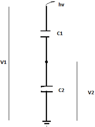
a) capacitance voltage divider for low voltage
b) capacitance voltage divider for medium voltage
c) capacitance voltage divider for high voltage
d) capacitance voltage divider for very high voltage
View Answer
Explanation: The given figure represents the equivalent circuit of capacitance voltage divider for very high voltage. C1 is the capacitance between the high voltage terminal and the test object. C2 involves the lead capacitance, input capacitance of CRO and other ground capacitances.
10. In pure capacitance dividers, loading on the source is negligible.
a) True
b) False
View Answer
Explanation: The main advantage of pure capacitance dividers is that the loading on a source is negligible. But the divider ratio gets affected whenever there is small disturbance is the location of the capacitor or electrode or presence of any stray object.
Sanfoundry Global Education & Learning Series – High Voltage Engineering.
To practice all areas of High Voltage Engineering, here is complete set of Multiple Choice Questions and Answers.
If you find a mistake in question / option / answer, kindly take a screenshot and email to [email protected]
