This set of High Voltage Engineering Multiple Choice Questions & Answers (MCQs) focuses on “Voltage Multiplier Circuit”.
1. The output of a cascaded rectifier is ______
a) 2nVmax
b) 2(n-1) Vmax
c) 2(n+1) Vmax
d) 4nVmax
View Answer
Explanation: The voltage is cascaded to give the output 2nVmax where n is the number of stages across the load. Instead of ac supply, valve-type pulse generators are used where in the pulses are generated in the anode circuit of the valve and are rectified.
2. What is the magnitude of the voltage produced across the coil L?
a) Vmax=\(I\sqrt{\frac{C_p}{L}}\)
b) Vmax=\(I\sqrt{\frac{L}{C_p}}\)
c) Vmax=\(I\sqrt{\frac{2 L}{C_p}}\)
d) Vmax=\(I\sqrt{\frac{4L}{C_p}}\)
View Answer
Explanation: A maximum voltage across the coil is produced when a triggering voltage pulse of ramp waveform is given to the valve to make it on and off. Cp is the stray capacitance across the coil of inductance L.
3. In case where a higher value of current is required ____________ rectifiers are used.
a) symmetrical
b) asymmetrical
c) symmetrical cascaded
d) asymmetrical cascaded
View Answer
Explanation: Symmetrical cascaded rectifiers are used where a higher value of current is required. These consist of mainly two rectifiers in cascade. These rectifiers share the same smoothing column.
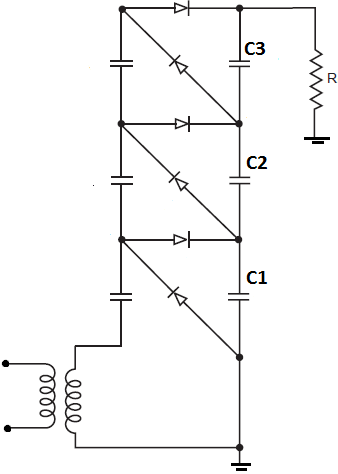
4. In the given figure of voltage multiplier circuit C1, C2, C3 represents the oscillating column.

a) True
b) False
View Answer
Explanation: The voltage across the column of capacitors consisting of C1, C2, C3, keeps on oscillating as there is alteration in the supply voltage. Hence, the voltage is not constant. This column, therefore, is known as oscillating column.
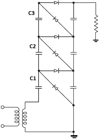
5. In the given figure of voltage multiplier circuit, C1, C2, C3 represents the smoothening column.
a) True
b) False
View Answer
Explanation: In the given figure of voltage multiplier circuit C1, C2, C3 represents the smoothening column. Since the voltage across these capacitors remains the same even if the supply voltage alternates, it is known as the smoothening column.
6. The optimum number of stages for a voltage multiplier circuit is _____
a) \(n_{opt}=\sqrt{\frac{V_{max} C}{I}}\)
b) \(n_{opt}=\sqrt{\frac{V_{max} f C}{I}}\)
c) \(n_{opt}=\sqrt{\frac{V_{max} f}{I}}\)
d) \(n_{opt}=\sqrt{2\frac{V_{max} f C}{I}}\)
View Answer
Explanation The optimum number of stages for a voltage multiplier circuit is \(n_{opt}=\sqrt{\frac{V_{max} f C}{I}}\), where Vmax is the maximum voltage, f is the frequency and C is the capacitance.
7. The symmetrical cascaded rectifier has a _____ voltage drop and also a _____ voltage ripple than the simple cascade.
a) smaller, smaller
b) larger, larger
c) larger, smaller
d) smaller, larger
View Answer
Explanation: The symmetrical cascaded rectifier has a smaller voltage drop and also a smaller voltage ripple than the simple cascade. Symmetrical cascaded rectifiers are used when higher value of current is required.
8. What is the voltage across the capacitor C1 shown in the figure?
a) 2Vmax
b) 4Vmax
c) Vmax
d) n Vmax
View Answer
Explanation: The given figure shows the circuit of a Cockroft-Walton voltage multiplier circuit.C1, C2, C3 represents the capacitors of the oscillating column. The voltage across the capacitor C1 shown in the figure is Vmax. where Vmax is the maximum voltage. Voltage across all the other capacitor is 2Vmax.
9. The Cockroft -Walton circuit produces _____
a) high DC voltage
b) low DC voltage
c) high AC voltage
d) low AC voltage
View Answer
Explanation: The Cockroft – Walton is an electric circuit that is used to produce high DC voltage. It is a voltage multiplier circuit whose input is a low voltage AC or pulsating input.
10. How the sag at higher stages can be reduced in a voltage multiplier circuit?
a) by increasing the capacitance in the lower stages
b) by increasing the capacitance in the higher stages
c) by decreasing the capacitance in the lower stages
d) by decreasing the capacitance in the higher stages
View Answer
Explanation: The sag at higher stages can be reduced in a voltage multiplier circuit by increasing the capacitance in the lower stages. The voltages of the higher stages begin to sag because of the electrical impedance of the capacitors in the lower stages.
Sanfoundry Global Education & Learning Series – High Voltage Engineering.
To practice all areas of High Voltage Engineering, here is complete set of Multiple Choice Questions and Answers.
If you find a mistake in question / option / answer, kindly take a screenshot and email to [email protected]
