This set of High Voltage Engineering Multiple Choice Questions & Answers (MCQs) focuses on “Resonant Transformer”.
1. What is the condition to have series resonance at power frequency ω?
a) (L1+L2)=1/ωC
b) (L1+L2)=1/2ωC
c) (L1+L2)=ωC
d) (L1+L2)=2ωC
View Answer
Explanation: The condition to have series resonance at power frequency ω is (L1+L2)=1/ωC where L1, L2 is the leakage inductance of the transformer and C is the capacitance of the high voltage object and ω is the power frequency.
2. The power requirements for a resonant transformer is less.
a) True
b) False
View Answer
Explanation: The main advantage of the resonant transformer is that the power requirements for a resonant transformer is less. It requires only 5-10% of the total kVA. It gives an output of pure sine wave.
3. The Q factor of the circuit gives the magnitude of __________ across the test object under resonance conditions.
a) voltage division
b) voltage multiplication
c) current division
d) current multiplication
View Answer
Explanation: The magnitude of the voltage multiplication is given by the Q factor of the resonance circuit. Under this condition, the secondary of the circuit is unity. This is the principle used in testing at very high voltages.
4. Which of the following transformer is suitable for cable testing and dielectric loss measurements?
a) cascaded transformer
b) resonant transformer
c) isolating transformer
d) single unit power transformer
View Answer
Explanation: Resonant transformer is suitable for cable testing and dielectric loss measurements. Resonant transformers are used on occasions requiring large current output and for testing at very high voltages.
5. What is the order of the Q-factor obtained in the series resonance circuits?
a) 100
b) 20
c) 40
d) 50
View Answer
Explanation: The order of the Q-factor obtained in the resonance circuits is 50. Hence, the output voltage is depended on the range of Q-factor. Parallel resonant transformers are more beneficial than the series resonant transformers.
6. The output voltage of single unit resonant transformer is up to _______
a) 100kV
b) 200kV
c) 40kV
d) 500kV
View Answer
Explanation: The output voltage of single unit resonant transformer is up to 500kV. It gives an output of pure sine wave. Cascaded unit is used for voltages up to 3000kV.
7. The output voltage of cascaded unit resonant transformer is up to _______
a) 1000kV
b) 3000kV
c) 4000kV
d) 50000kV
View Answer
Explanation: The output voltage of cascaded unit resonant transformer is up to 3000kV. It gives an output of pure sine wave. Single unit is used for voltages up to 500kV.
8. Separate compensating reactors are required in the resonant transformer.
a) True
b) False
View Answer
Explanation: Separate compensating reactors are not required in the resonant transformer. It is similar to a test transformer. Non requirement of the compensating requires reduces the overall weight of the circuit.
9. Complete balance of ampere turn takes place under _________
a) series resonance condition
b) series-parallel resonance condition
c) parallel resonance condition
d) parallel-series resonance condition
View Answer
Explanation: Under parallel resonance condition, the complete balance of the ampere turn takes place. Under all other conditions of the transformer, unbalance ampere turn takes place and results in hotspot due to large circulating currents.
10. The specific weight of a series resonant transformer lies between ________
a) 3 and 6 kg/kVA
b) 6 and 10 kg/kVA
c) 8 and 12 kg/kVA
d) 9 and 15 kg/kVA
View Answer
Explanation: The specific weight of a series resonant transformer lies between 3 and 6 kg/kVA. The specific of a cascaded transformer lies between 10 and 20 kg/kVA.
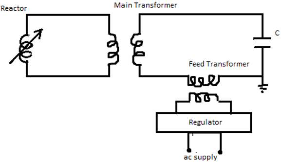
11. Identify the following diagram.
a) parallel resonant transformer
b) series resonant transformer
c) cascaded transformer
d) series-parallel resonant transformer
View Answer
Explanation: The given figure represents series resonant transformer. Secondary is rated for the full test voltage. C represents the load capacitance.
12. Identify the elements in the given figure.
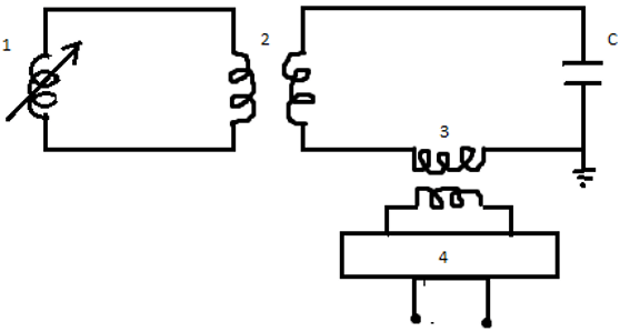
a) 1-reactor, 2-main transformer, 3-feed transformer, 4-regulator
b) 1- regulator, 2- main transformer, 3-feed transformer, 4-reactor
c) 1- regulator, 2- feed transformer, 3-main transformer, 4-reactor
d) 1-reactor, 2-feed transformer, 3-main transformer, 4-regulator
View Answer
Explanation: The given figure represents the series resonance circuit. The correct description of the elements is 1-reactor, 2-main transformer, 3-feed transformer, 4-regulator. C represents the load capacitance.
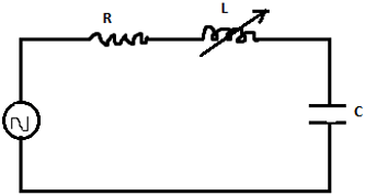
13. Identify the following figure.
a) equivalent circuit of parallel resonant transformer
b) equivalent circuit of series resonant transformer
c) equivalent circuit of cascaded transformer
d) equivalent circuit of series-parallel resonant transformer
View Answer
Explanation: The given figure represents equivalent circuit of series resonant transformer. Secondary is rated for the full test voltage. C represents the load capacitance. The resistance has a usually a low value.
Sanfoundry Global Education & Learning Series – High Voltage Engineering.
To practice all areas of High Voltage Engineering, here is complete set of Multiple Choice Questions and Answers.
If you find a mistake in question / option / answer, kindly take a screenshot and email to [email protected]
