This set of High Voltage Engineering Multiple Choice Questions & Answers (MCQs) focuses on “Generation of High DC and AC Voltages”.
1. Rectifier circuits for producing high dc voltages from ac sources may be ______
a) half wave rectifiers
b) full wave rectifiers
c) voltage double-type rectifiers
d) half wave, full wave or voltage double-type rectifiers
View Answer
Explanation: The simplest circuit for the generation of high direct voltage is the half wave rectifier. Full wave rectifier is a circuit, which converts an ac voltage into a pulsating dc voltage using both half cycles of the applied ac voltage. A voltage double type rectifier produces a DC multiple (2) of the AC peak input voltage.
2. Semiconductor or solid-state devices are available for peak inverse voltages up to ______
a) 250 kV
b) 25kV
c) 20kV
d) 50kV
View Answer
Explanation: The rectifier can be an electron tube or a solid-state device. Single electron tubes are available for peak voltages up to 250 kV. Semiconductor or solid-state devices are available up to a peak voltage of 20 kV. Several units are assigned in series for higher voltages.
3. Which among the following diodes is preferred for high-voltage rectifiers?
a) Gunn diode
b) Selenium diode
c) Silicon diode
d) Laser diode
View Answer
Explanation: Silicon diode is a crystal diode that uses silicon as a semiconductor. Silicon diodes with peak inverse voltage(PIV) of 1kV to 2kV are used in high-voltage rectifiers. PIV refers to the maximum voltage a diode can withstand in the reverse-biased direction before breakdown.
4. What is the magnitude of the charge delivered by the capacitor in a rectifier circuit?
a) Q=C (Vmax + Vmin)
b) Q=C (Vmax – Vmin)
c) Q=C Vmax
d) Q=C Vmin
View Answer
Explanation: At any time, the voltage of the capacitor is V and it decreases by an amount of dV over
the time dt, then charge delivered by the capacitor during this time is dQ = CdV. It is assumed that the voltage changes from Vmax to Vmin. Hence, on integration we get the charge delivered by the capacitor in a rectifier circuit as Q=C (Vmax– Vmin).
5. Both half wave and full wave rectifier circuits produce a dc voltage more than the ac maximum voltage.
a) True
b) False
View Answer
Explanation: Both half wave and full wave rectifier circuits produce a dc voltage less than the ac maximum voltage. When higher voltages are needed, a voltage doubler or cascaded doubler circuits are used.
6. The ripple voltage is larger for a half-wave rectifier than a full-wave rectifier.
a) True
b) False
View Answer
Explanation: Since the discharge period in the case of half–wave rectifier is larger, the ripple voltage is larger for a half-wave rectifier than a full-wave rectifier. The ripple voltage depends on the supply frequency, the time constant and the reactance of the supply transformer.
7. What is the relationship between ripple voltage δV and product fC?
a) δV=\(\frac{I}{fC}\)
b) δV=\(\frac{I}{2fC}\)
c) δV=\(\frac{fC}{I}\)
d) δV=\(\frac{I}{4fC}\)
View Answer
Explanation: Equation δV=\(\frac{I}{2fC}\) shows that the ripple in a rectifier output depends upon the load current and the circuit parameter like frequency(f) and capacitance(C). The product fC is, therefore, an important design factor for the rectifiers.
8. Why do we provide an additional resistance in a rectifier circuit?
a) to limit the charging current
b) to enhance the charging current
c) to decrease the pulsating voltage
d) to increase the pulsating voltage
View Answer
Explanation: An additional resistance in a rectifier circuit is provided to limit the charging current. It is usually connected in series with the secondary of the transformer in the rectifier circuit.
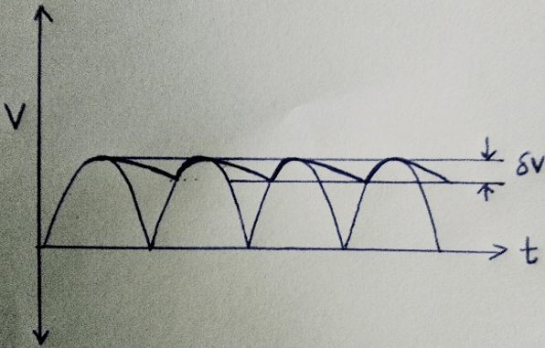
9. Identify the following output voltage.

a) Output with half-wave rectifier and capacitor filter
b) Output with full-wave rectifier and capacitor filter
c) Output with half-wave rectifier
d) Output with full-wave rectifier
View Answer
Explanation: The line shows the discharging current of the capacitor. For half-wave rectifiers, the ripple frequency is equal to the supply frequency and for full-wave rectifier, it is twice that value.
10. Which is the simplest voltage doubler circuit?
a) Greinacher
b) Cockroft-Walton
c) Cascaded
d) Cascaded and Cockroft-Walton
View Answer
Explanation: Greinacher is the simplest voltage doubler circuit. It comprises of two resistors and two capacitors. Cockroft–Walton and cascade circuit are voltage multiplier circuits.
Sanfoundry Global Education & Learning Series – High Voltage Engineering.
To practice all areas of High Voltage Engineering, here is complete set of Multiple Choice Questions and Answers.
If you find a mistake in question / option / answer, kindly take a screenshot and email to [email protected]
