This set of Flexible Manufacturing System Multiple Choice Questions & Answers (MCQs) focuses on “Ladder Logic Diagrams”.
1. Which of the following is the principal technique for setting up the control programs in programmable logic controllers?
a) Technical Diagram
b) Ladder Logic Diagram
c) Truth Table
d) Control Chart
View Answer
Explanation: The principal technique used for setting up the control programs in programmable logic controllers is known as Ladder Logic Diagram. It is a way to represent the components present in the control system.
2. Which of the following are located at the left of the ladder logic diagram?
a) Handling Device
b) Controller
c) Output Loads
d) Input Contacts
View Answer
Explanation: To the left of the ladder logic diagram, input contacts are located. The inputs typically used in a control system include on or off sensors like limit switches, photo detectors, relay contacts, timers and other binary contact devices.
3. Vertical lines in the ladder logic diagram are used to represent the components of the control system.
a) True
b) False
View Answer
Explanation: Horizontal Lines in the ladder logic diagram are used to represent the different components of the control system. These horizontal lines are also termed as rungs connected to either end of the vertical lines.
4. Which of the following are located to the right of the ladder logic diagram?
a) Moderators
b) Output Loads
c) Input Contacts
d) Resistors
View Answer
Explanation: To the right of the ladder logic diagram, output loads are located. Output loads typically used in the control system include lamps, solenoids, alarms, motors and lamps. The output of the control system us obtained through loads.
5. Which is represented through vertical lines in the ladder logic diagram?
a) Power
b) Input
c) Load
d) Storage Device
View Answer
Explanation: The vertical lines in the ladder logic diagram represent the power to the control system. It is to be noted that the power remains the same and is equally transferred for all the input contacts used in the system.
6. Which of the following symbol is used to denote the normal open contacts in the system?
a)
![]()
![]()
b)
![]()
![]()
c)
![]()
![]()
d)
![]()
![]()
View Answer
Explanation:
7. Which of the following symbol is used to denote the normal closed contacts in the system?
a)
![]()
![]()
b)
![]()
![]()
c)
![]()
![]()
d)
![]()
![]()
View Answer
Explanation:
8. Which of the following denotes the output loads of the system?
a)
![]()
![]()
b)
![]()
![]()
c)
![]()
![]()
d)
![]()
![]()
View Answer
Explanation:
9. Which of the following symbol denotes counter?
a)
![]()
![]()
b)
![]()
![]()
c)
![]()
![]()
d)
![]()
![]()
View Answer
Explanation: Up/Down Counter combines the operations of up and down counter. To achieve the up/down operation, it is necessary a combinational circuit to be designed and used between each pair of flip-flop.
10. Which of the following symbol denotes timer?
a)
![]()
![]()
b)
![]()
![]()
c)
![]()
![]()
d)
![]()
![]()
View Answer
Explanation:
11. Which of the following contact remains open until it is activated?
a) Normally Closed Contact
b) Normally Open Contact
c) Activated Contact
d) Modulated Contact
View Answer
Explanation: The contact which remains open until it is activated is known as Normally Open Contact. The signal to the system will be in OFF mode in general. Once it is activated, the current to the system will be turned ON.
12. Which of the following contact remains closed until it is activated?
a) Vibrator Contact
b) Articulated Contact
c) Normally Open Contact
d) Normally Closed Contact
View Answer
Explanation: The Contact which remains closed until it is activated is known as Normally Closed contact. The Signal to the system will be transmitted until activated to stop the transmission by the user i.e., the current flows through the contact.
13. Timer performs like a logical NOT gate.
a) True
b) False
View Answer
Explanation: Normally Closed Contact performs like a logical NOT gate. Logical NOT gate reverses the input signal before producing the output. Similarly, Normally Closed Contact gives the output in converse to the input given.
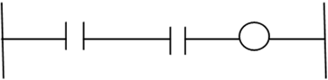
14. Which of the logic gate is represented in the given ladder logic diagram?
a) XOR
b) NOT
c) OR
d) AND
View Answer
Explanation: Ladder Logic Diagram using logical AND gate is represented as:
Logical OR, logical NOT and logical XOR gates cannot be represented using this symbol.
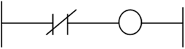
15. Which of the logic gate is represented in the given ladder logic diagram?
a) XOR
b) NOT
c) OR
d) AND
View Answer
Explanation: Ladder Logic Diagram using logical NOT gate is represented as:
Logical XOR, logical OR and logical AND gates cannot be represented using this symbol.
Sanfoundry Global Education & Learning Series – Flexible Manufacturing System.
To practice all areas of Flexible Manufacturing System, here is complete set of 1000+ Multiple Choice Questions and Answers.
If you find a mistake in question / option / answer, kindly take a screenshot and email to [email protected]
