This set of FACTS Multiple Choice Questions & Answers (MCQs) focuses on “Power Semiconductor Devices”.
1. Diode is a ________ device.
a) single-layered
b) two-layered
c) three-layered
d) four-layered
View Answer
Explanation: Diode is a two-layered device. It possesses two terminals. They are anode and cathode. It finds its application in FACTS devices.
2. Transistor is a ________ device.
a) single-layered
b) two-layered
c) three-layered
d) four-layered
View Answer
Explanation: Transistor is a three-layered device. It possesses three terminals. They are collector, emitter and base. The polarity of these terminals with respect to each other decides the configuration of the device.
3. Thyristor is a ________ device.
a) single-layered
b) two-layered
c) three-layered
d) four-layered
View Answer
Explanation: Thyristor is a four-layered device. It possesses three terminals. They are anode, cathode and gate. It finds its application in FACTS devices, especially for its controlled gate turn-on capability.
4. Identify the terminal A of the given figure.
a) Cathode
b) Anode
c) Gate
d) Drain
View Answer
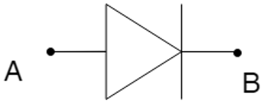
Explanation: The given figure shows a diode. The terminal A in the given figure is the anode. This terminal should be kept positive for forward direction conduction. This terminal when kept negative, blocks the conduction of current.
5. Identify the terminal B of the given figure.
a) Cathode
b) Anode
c) Gate
d) Drain
View Answer
Explanation: The given figure shows a p-n diode. The terminal B in the given figure is the cathode. This terminal should be kept negative for forward direction conduction. This terminal when kept positive, blocks the conduction of current.
6. Identify the terminal A of the given figure.
a) Cathode
b) Anode
c) Gate
d) Drain
View Answer
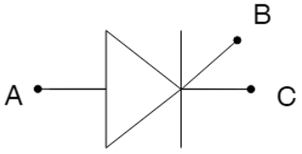
Explanation: The given figure shows a thyristor. The terminal A in the given figure is the anode. This terminal should be kept positive for forward direction conduction in the latched condition of the device. This terminal when kept negative, blocks the conduction of current through it.
7. Identify the terminal B of the given figure.
a) Cathode
b) Anode
c) Gate
d) Drain
View Answer
Explanation: The given figure shows a thyristor. The terminal B in the given figure is the gate. This terminal controls the switching-on and in some cases the switching-off of the device. A turn-on current or voltage signal is applied to this electrode for the required action of the device.
8. Identify the terminal C of the given figure.
a) Cathode
b) Anode
c) Gate
d) Drain
View Answer
Explanation: The given figure shows a thyristor. The terminal C in the given figure is the cathode. This terminal should be kept negative for forward direction conduction in the latched condition of the device. This terminal when kept positive, blocks the conduction of current through it.
9. Identify the terminal A of the given figure.
a) Emitter
b) Collector
c) Gate
d) Base
View Answer
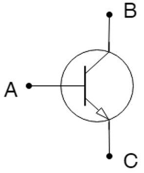
Explanation: The given figure shows a transistor. The terminal A in the given figure is the base. A turn-on current or voltage signal is applied to this electrode for the device to conduct properly. It should be fed maintaining proper polarity as per the configuration demands.
10. Identify the terminal B of the given figure.
a) Emitter
b) Collector
c) Gate
d) Base
View Answer
Explanation: The given figure shows a BJT. The terminal B in the given figure is the collector. This collector forms a pn junction with the base. This terminal should be of compatible polarity as per the configuration of the device.
11. Identify the terminal C of the given figure.
a) Emitter
b) Collector
c) Gate
d) Base
View Answer
Explanation: The given figure shows a NPN transistor. The terminal C in the given figure is the emitter. This emitter forms a pn junction with the base. Emitter is highly doped with respect to the other terminals.
12. Identify the terminal B of the given figure.
a) Emitter
b) Collector
c) Gate
d) Base
View Answer
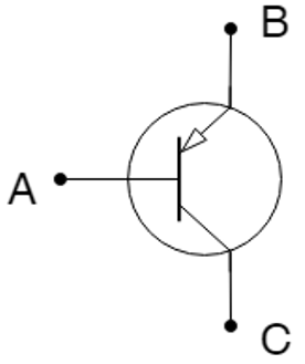
Explanation: The given figure shows a PNP transistor. The terminal B in the given figure is the emitter. This emitter always carries the arrow symbol irrespective of its configured polarity. The arrow is either pointing inwards or outwards.
13. Identify the terminal A of the given figure.
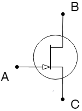
a) Source
b) Collector
c) Drain
d) Gate
View Answer
Explanation: The given figure shows an n-channel JFET. The terminal A in the given figure is the gate. This gate always carries the arrow symbol irrespective of its configured polarity. The arrow is either pointing inwards or outwards.
14. Identify the terminal B of the given figure.
a) Emitter
b) Collector
c) Drain
d) Gate
View Answer
Explanation: The given figure shows a junction field effect transistor. The terminal B in the given figure is the drain. This ohmic electrical connection can be at either end of the device. The terms ʻemitterʼ and ʻcollectorʼ given in the options are not applicable for a transistor.
15. Identify the terminal C of the given figure.
a) Source
b) Collector
c) Emitter
d) Gate
View Answer
Explanation: The given figure shows a FET. The terminal C in the given figure is the source. This ohmic electrical connection can be at either end of the device. The terminals C and B can be used interchangeably irrespective of the polarity configured in the channel.
Sanfoundry Global Education & Learning Series – Flexible AC Transmission System (FACTS).
To practice all areas of Flexible AC Transmission System (FACTS), here is complete set of 1000+ Multiple Choice Questions and Answers.
If you find a mistake in question / option / answer, kindly take a screenshot and email to [email protected]
