This set of FACTS Multiple Choice Questions & Answers (MCQs) focuses on “AC Transmission Interconnections – Set 3”.
1. AC power transmission systems are interconnected to ensure ________
a) only reliability
b) only economy
c) both reliability and economy
d) hypothetical conditions
View Answer
Explanation: AC power transmission systems are interconnected to ensure both reliability and economy. Therefore, these interconnections ensure system operation minimizing or erasing the impact of a loss or failure of element(s) on it. Also the economy coupled with large power plants can be utilized wisely instead of setting-up several small ones.
2. For ideal transmission active power should be ________ apparent power.
a) equal to
b) greater than
c) less than
d) equal to or less than
View Answer
Explanation: For ideal transmission active power should be equal to apparent power. In this ideal condition reactive power should be equal to zero. Therefore, the power factor for an ideal transmission should be unity.
3. For ideal transmission reactive power should be ________
a) equal to apparent power
b) greater than active power
c) equal to unity
d) equal to zero
View Answer
Explanation: For ideal transmission reactive power should be equal to zero. In this ideal condition active power should be equal to apparent power. In other words, the power factor for an ideal transmission should be unity.
4. For ideal transmission apparent power should be ________
a) equal to active power
b) equal to apparent power
c) equal to unity
d) equal to zero
View Answer
Explanation: For ideal transmission apparent power should be equal to active power because in this ideal condition reactive power should be equal to zero. Therefore, the power factor for an ideal transmission should be unity.
5. For ideal transmission power factor should be ________
a) equal to zero
b) greater than unity
c) less than zero
d) equal to unity
View Answer
Explanation: For ideal transmission reactive power should be equal to zero resulting in apparent power to be equal to active power. Therefore, the power factor for an ideal transmission should be unity as cos0 is equal to one.
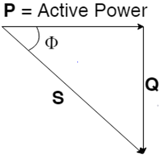
6. In the following figure what does Q indicate?

a) Reactive Power
b) Apparent Power
c) Maximum Power
d) Optimum Power
View Answer
Explanation: The figure here is the power triangle. In this power triangle we see the relationship between different types of power which we encounter during transmission of electric power. In it P is the Active Power, Q is the Reactive Power. This reactive power can be due to either capacitance or inductance of the circuit concerned.
7. In the below figure what does S signify?

a) Reactive Power
b) Apparent Power
c) Maximum Power
d) Optimum Power
View Answer
Explanation: During analysis of flow of electric power, we encounter different types of power. This figure here actually demonstrates the relationship between them and is known as power triangle. In it P is the Active Power, S is the Apparent Power. This apparent power is the indication of the total power utilized during the transmission of electric power.
8. In the given figure what does cosΦ (cosine of angle phi) indicate?

a) Reactive Power
b) Apparent Power
c) Maximum Power
d) Power Factor
View Answer
Explanation: The triangle is called power triangle. It is the proof that Active Power, Reactive Power and Apparent Power exists during the flow of electric power. In this triangle the base angle Φ is actually the angle made by the active power P with the apparent power S. The cosine of this angle Φ (phi), i.e. cosΦ is known as the power factor.
9. In the equation v = \(\sqrt2\)V sin wt, what does V indicate?
a) Instantaneous voltage
b) RMS voltage
c) Maximum voltage
d) Average voltage
View Answer
Explanation: The equation of a voltage sine wave is given by v =Vmsin wt, where Vm is the maximum value. Again RMS value VRMS =Vm\(\sqrt2\). On replacing the maximum value with RMS one, we get the equation v = \(\sqrt2\)VRMSsin wt . Hence, in the given equation V indicates RMS voltage.
10. For three phase supply through AC transmission lines what does V and I stand for in the equation P = \(\sqrt3\)VI cos θ?
a) line value
b) phase value
c) maximum value
d) minimum value
View Answer
Explanation: A three phase electric supply through AC transmission lines is given by the equation P = 3VphIph cos θ. Here Vph and Iph are the phase values of voltage and current; cos θ is the power factor. In delta connection of supply Vph = VL and Iph = IL/\(\sqrt3\). In star connection of supply Iph = IL and Vph = VL/\(\sqrt3\). Substituting these values we get the equation P = \(\sqrt3\)VLILcos θ, irrespective of star or delta connection.
Sanfoundry Global Education & Learning Series – Flexible AC Transmission System (FACTS).
To practice all areas of Flexible AC Transmission System (FACTS), here is complete set of 1000+ Multiple Choice Questions and Answers.
If you find a mistake in question / option / answer, kindly take a screenshot and email to [email protected]
