This set of FACTS Multiple Choice Questions & Answers (MCQs) focuses on “Power Semiconductor Devices – IGCT, IGBT and MCT – Set 2”.
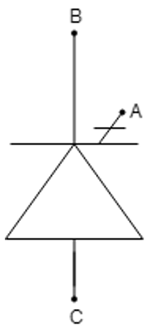
1. Identify the terminal C of the given figure.
a) cathode
b) anode
c) turn-on gate
d) turn-on & turn-off gate
View Answer
Explanation: The given figure represents both a GCT and a GTO. The terminal C in the given figure is the anode. Though GCT and GTO shares the common equivalent circuit, they differ in operation and characteristic features.
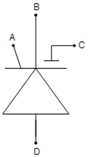
2. Identify the terminal C of the given figure.
a) cathode
b) anode
c) turn-on gate
d) turn-off gate
View Answer
Explanation: The given figure represents an MTO. The terminal C in the given figure is the turn-off gate. MTO is basically more efficient than conventional GTO.
3. Identify the terminal A of the given figure.
a) cathode
b) anode
c) turn-on gate
d) turn-off gate
View Answer
Explanation: The given figure represents an MTO. The terminal A in the given figure is the turn-on gate. Structural analysis reveals that MTO contains two types of transistors.
4. Identify the terminal B of the given figure.
a) cathode
b) anode
c) turn-on gate
d) turn-off gate
View Answer
Explanation: The given figure represents an MTO. The terminal C in the given figure is the cathode. Structurally the MOSFETs are fabricated on the silicon wafer surrounding the GTO.
5. Identify the terminal D of the given figure.
a) cathode
b) anode
c) turn-on gate
d) turn-off gate
View Answer
Explanation: The given figure represents an MTO. The terminal C in the given figure is the anode. Incorporating MOSFETs righteously, MTO succeeds to minimize the stray inductance in its gate-cathode loop.
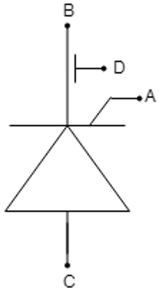
6. Identify the terminal A of the given figure.
a) cathode
b) anode
c) turn-on gate
d) turn-off gate
View Answer
Explanation: The given figure represents an ETO. The terminal A in the given figure is the turn-on gate. ETO has two gate terminals for its functioning.
7. Identify the terminal D of the given figure.
a) cathode
b) anode
c) turn-on gate
d) turn-off gate
View Answer
Explanation: The given figure represents an ETO. The terminal D in the given figure is the turn-off gate. An ETO houses only one GTO in its structure.
8. Identify the terminal B of the given figure.
a) cathode
b) anode
c) turn-on gate
d) turn-off gate
View Answer
Explanation: The given figure represents an ETO. The terminal B in the given figure is the cathode. An ETO houses two types of MOSFETS in its structure.
9. Identify the terminal C of the given figure.
a) cathode
b) anode
c) turn-on gate
d) turn-off gate
View Answer
Explanation: The given figure represents an ETO. The terminal C in the given figure is the anode. ETO incorporates both the GTO and MOSFET.
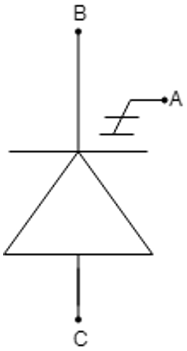
10. Identify the terminal C of the given figure.
a) cathode
b) anode
c) turn-on gate
d) turn-off gate
View Answer
Explanation: The given figure represents an MCT. The terminal C in the given figure is the anode. MCT represents turn-off thyristor with low on-state and switching losses.
11. Identify the terminal B of the given figure.
a) cathode
b) anode
c) turn-on gate
d) turn-off gate
View Answer
Explanation: The given figure represents an MCT. The terminal B in the given figure is the cathode. With the application of positive voltage to the gate with respect to the cathode, MCT is turned-on.
12. Identify the terminal A of the given figure.
a) cathode
b) anode
c) turn-on & turn-off gate
d) turn-off gate
View Answer
Explanation: The given figure represents an MCT. The terminal A in the given figure is the turn-on & turn-off gate. When the gate voltage is made negative, it unlatches the thyristor to off-condition.
13. GCT ensures its fast turning-off.
a) True
b) False
View Answer
Explanation: GCT ensures its fast turning-off. It is designed to draw out all the current from the cathode into the gate in very short time (say 1microsec). It employs a fast-rising and high-current as the required gate pulse.
14. GCT and GTO are used to designate same device.
a) True
b) False
View Answer
Explanation: GCT and GTO are NOT used to designate same device. It is true that both GCT and GTO shares same equivalent circuit; but they differ from each other. GCT is a hard-switched GTO with a very fast acting drive for gate.
15. GCT is an advanced version of IGCT.
a) True
b) False
View Answer
Explanation: GCT is NOT an advanced version of IGCT. Basically IGCT is a device with further advancement on GCT. The fabrication of IGCT comes with a multilayered printed circuit board along with gate drive housed with the main device. It may also house a reverse diode.
Sanfoundry Global Education & Learning Series – Flexible AC Transmission System (FACTS).
To practice all areas of Flexible AC Transmission System (FACTS), here is complete set of 1000+ Multiple Choice Questions and Answers.
If you find a mistake in question / option / answer, kindly take a screenshot and email to [email protected]
