This set of Power Electronics Multiple Choice Questions & Answers (MCQs) focuses on “Dual Converters-1”.
1. Dual converters provide
a) two quadrant operation
b) three quadrant operation
c) four quadrant operation
d) none of the mentioned
View Answer
Explanation: Dual converters provide four quadrent operation, which means voltage can be positive or negative and so can be the current. Hence, AC-DC, DC-AC any converter configuration can be used.
2. A dual converters has
a) two full converters in series
b) two half converters in series
c) two full converters in anti-parallel
d) two half converters in anti-parallel
View Answer
Explanation: Dual converters have two full converters connected in anti-parallel which provides a four quadrant operation.
3. The major advantage of using dual converters is that
a) it is cheaply available
b) it has better pf
c) no mechanical switch is required to change the mode of operation
d) its operating frequency is very high
View Answer
Explanation: No mechanical arrangement is required to change from inverter to converter and converter to inverter, which was required in earlier methods.
4. The four quadrant operation of dual converters can be obtained by
a) moving the mechanical lever
b) adding inductance to the circuit
c) changing the firing angle value
d) none of the mentioned
View Answer
Explanation: The four quadrant operation can be obtained simply by adjusting appropriate values of firing angles for both the connected converters.
5. A single full converter alone can given a
a) four quadrant operation
b) three quadrant operation
c) two quadrant operation
d) none of the mentioned
View Answer
Explanation: A single full converter alone gives two quadrent operation, hence for all four quadrant operation two full converter circuits are connected in anti-parallel.
6. Find the error in the below given dual converter circuit.
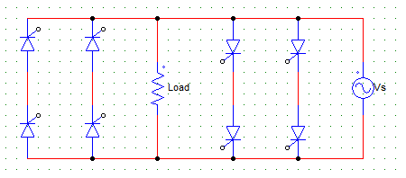
i) Load is not connected in the right position
ii) Only 4 SCRs must be used
iii) Voltage source is not connected for one of the converter circuit
iv) Voltage source is not connected in the proper place
a) All 4
b) Both (i) and (iv)
c) Both (iii) and (iv)
d) Both (ii) and (iii)
View Answer
Explanation: The right connection for single-phase dual converter is shown below.
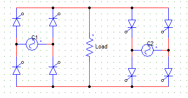
7. In the below given circuit, the right side converter C2 operates in the ___ and ___ quadrant.
a) second, fourth
b) first, fourth
c) second, third
d) first, third
View Answer
Explanation: The C2 converter will supply the load current in direction opposite to that supplied by the converter C1. For converter C2, when α> 90 it operates in 2nd quadrant and if α<90 both current and voltage are negative, C2 is in inverter mode and operates in 3rd quadrant.
8. Name the below given circuit.
a) Single-phase dual converter circulating current type
b) Single-phase dual converter non-circulating current type
c) Three-phase dual converter non-circulating current type
d) Three-phase dual converter circulating current type
View Answer
Explanation: The circuit is a single phase dual converter circuit. As the there is no reactor (inductor) in series, it is a non-circulating type.
9. For a single-phase dual converter, with converters C1 and C2 connected in anti-parallel, which relation among the following is true to keep the average voltages from C1 and C2 equal? C1 and C2 have firing angles α1 and α2 respectively.
a) α1 = α2
b) α1 + α2 = 360°
c) α1 + α2 = 180°
d) none of the mentioned
View Answer
Explanation: By maintaining α1 + α2 = 180°, one converter can operate as converter and another as an inverter hence, the average output voltages are equal . This can be proved as follows
Vom cos α1 = Vom cos α2
Vom = 2Vm/π . . (Vm for both the converters is same)
cos α1 = cos α2
cos α1 = cos (180 – α2)
α1 + α2 = 180°.
10. In non-circulating current mode dual converters, the circulating current is avoided by
a) connecting a series reactor
b) maintaining α1 + α2 = 180°
c) operating only one converter
d) adding an extra SCR
View Answer
Explanation: Reactor is added in circulating current mode not in non-circulating mode. The circulating current is avoided by using only one of the converters.
Sanfoundry Global Education & Learning Series – Power Electronics.
To practice all areas of Power Electronics, here is complete set of 1000+ Multiple Choice Questions and Answers.
If you find a mistake in question / option / answer, kindly take a screenshot and email to [email protected]
