This set of Power Electronics Multiple Choice Questions & Answers (MCQs) focuses on “Firing Circuits – 2”.
1. In a resistance firing circuit the firing angle
a) cannot be greater than 120°
b) cannot be greater than 90°
c) cannot be greater than 180°
d) cannot be greater than 160°
View Answer
Explanation: The R firing circuits cannot be used for alpha greater than 90 degrees.
2. For a R firing circuit, the maximum value of source voltage is 100 V. Find the resistance to be inserted to limit the gate current to 2 A.
a) 5 Ω
b) 50 Ω
c) 500 Ω
d) 0.5 Ω
View Answer
Explanation: R = 100/2 = 50 Ohm.
3. The diode in the R firing circuit
a) ensures that the gate voltage is a half wave DC pulse
b) ensures that the gate voltage is a full wave DC pulse
c) ensures that the gate voltage is a half wave AC pulse
d) ensures that the gate voltage is a full wave AC pulse
View Answer
Explanation: The diode is placed between the resistances and gate which ensures that the current flows in one direction only.
4. In case of an RC half wave triggering circuit, the firing angle can be ideally varied between
a) 0 to 180
b) 0 to 90
c) 0 to 120
d) 0 to 360
View Answer
Explanation: Unlike the R firing circuit, the RC firing circuits can be used to obtain firing angle greater than 180. Although practically 0 and 180 degree is improbable.
5. In the figure given below, the resistance R1 is used to
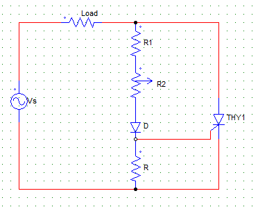
a) keep the gate circuit voltage drop minimum
b) limit the gate current to a safe value when R2 = 0
c) limit the gate current to a safe value when R2 is very large
d) allow the gate power dissipation
View Answer
Explanation: As R2 is the variable, R1 makes sure that the current does not exceed the maximum value when R2 is kept at zero position.
6. In case of a R firing with R2 as the variable resistance, Vgp (peak of gate voltage) and Vgt (gate triggering voltage) the value of R2 is so adjusted such that
a) Vgp = Vgt
b) Vgp > Vgt
c) Vgp < Vgt
d) Vgp = Vgt = 0
View Answer
Explanation: For turning on the device, the peak of gate voltage must be equal to the gate triggering voltage.
7. In case of a R firing circuit with Vgp > Vgt
a) α = 90°
b) α > 90°
c) α < 90°
d) α = 0°
View Answer
Explanation: For the values of Vgp great than the gate triggering voltage the firing angle is less than 90°. And for Vgp = Vgt the firing angle is equal to 90°. Α cannot go beyond 90° in case of a R firing circuit.
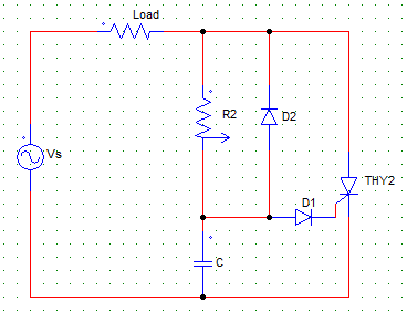
8. The figure shown below is that of a
a) R firing circuit
b) RC half-wave firing circuit
c) RC full-wave firing circuit
d) UJT triggering circuit
View Answer
Explanation: The given circuit is a RC half-wave firing circuit.
9. The figure shown below is that of an RC firing circuit.
In case of negative cycle at Vs, the capacitor C
a) charges through D2 with lower plate negative
b) charges through D1 with lower plate negative
c) charges through D2 with lower plate positive
d) charges through D1 with lower plate positive
View Answer
Explanation: The current flows through Vs+ – C – D2 – Load – Vs.
10. Find the value of R in case of an RC firing circuit which is to be turned on with a source voltage of 150 V and the following parameters.
Igt = 2A
Vd = 1.5V
Vgt = 125 V
a) 11.75 Ω
b) 54.25 Ω
c) 96 Ω
d) 5 Ω
View Answer
Explanation:
R = (Vs-Vgt-Vd)/Igt.
Sanfoundry Global Education & Learning Series – Power Electronics.
To practice all areas of Power Electronics, here is complete set of 1000+ Multiple Choice Questions and Answers.
If you find a mistake in question / option / answer, kindly take a screenshot and email to [email protected]
