This set of Power Electronics Multiple Choice Questions & Answers (MCQs) focuses on “Diode Circuits-3”.
1. For the circuit shown in the figure below, consider the diode as an ideal diode & rms value of source voltage as Vs.
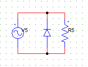
The output voltage waveform at R will have
a) zero value in the positive half cycle and a peak value of 1.414Vs in the negative half cycle
b) sine-wave nature with a peak value 1.414Vs
c) zero value in the negative half cycle and a peak value of 1.414Vs in the positive half cycle
d) sine-wave nature with a peak value Vs
View Answer
Explanation: The diode short circuits the load in the negative half cycle. The peak value in the positive half is 1.414 x Vs.
2. For the circuit shown in the figure below, Vs is the ac voltage source with peak value Vm. The waveform of the load voltage at the resistor will have
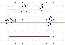
a) zero value in the positive half cycle and a peak value of –(Vm) in the negative half cycle
b) zero value in the negative half cycle and a peak value of –(Vm-V1) in the positive half cycle
c) zero value in the positive half cycle and a peak value of –(Vm+V1) in the negative half cycle
d) zero value in the positive half cycle and a peak value of –(Vm-V1) in the negative half
View Answer
Explanation: Diode is reversed biased in the positive half cycle. In the negative half cycle, apply KVL to get the value of peak voltage at the load.
3. For the circuit shown below,
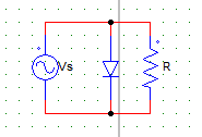
Vs=230V, Voltage drop across the diode (Vd) = 2V
The peak value of voltage at R in the positive and the negative half cycles are ___ & ___ respectively.
a) 323V,0V
b) 0V, 323V
c) 327V, 0V
d) 0V, 327V
View Answer
Explanation: Load is S.C in the positive half cycle hence, voltage is zero. In negative half the peak value is (230 x 1.414) – 2(drop across the diode) = 323 Volts.
4. For the circuit shown in the figure below, V9 is the AC voltage source with peak value Vm. The waveform of the load voltage at the resistor has a
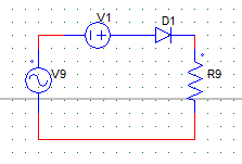
a) peak value of (Vm+V1) in the negative half cycle
b) peak value of (Vm-V1) in the positive half cycle
c) peak value of (Vm+V1) in the positive half cycle
d) peak value of (Vm-V1) in the negative half cycle
View Answer
Explanation: Diode is reversed biased in the negative half cycle. In the positive half cycle, apply KVL to get the value of peak voltage at the load. Peak value = Vm + V1, as V1 is aiding the positive anode of the diode.
5. The circuit shown below has the following parameters:
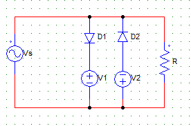
V1 = 8 Volts
V2 = 6 Volts
Vs = 10V/√2 (rms)
Voltage drop across D1 & D2 = 0.7 Volts
At the load (R), the peak value in the positive half cycle will be
a) 8.7 V
b) 6.7 V
c) 8 V
d) 10V/√2
View Answer
Explanation: In the positive half, only D1 is active. Hence use KVL, Vo = 8 + 0.7 Volts.
6. The circuit shown below has the following parameters:
Voltage drop across D1 & D2 = 0.7 Volts
V1 = 8 Volts
V2 = 6 Volts
Vs = 10V/√2 (RMS)
At the load (R), the peak value in the negative half cycle is
a) 8.7 V
b) 6.7 V
c) 8 V
d) 10V/√2
View Answer
Explanation: In the negative half, only D2 is active. Hence use KVL, Vo = 6 + 0.7 Volts.
7. Consider the diode to be an ideal one and Vo = Vr + Vdc during positive half cycle. Thus, during the negative half cycle
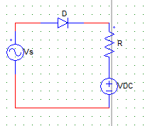
a) Vo = Vr
b) Vo = 0
c) Vo = Vdc+Vr
d) Vo = Vdc
View Answer
Explanation: During the negative half diode is not conducting hence Vr (voltage across the resistor) = 0. Vo = Vdc.
8. When a diode is connected in series with an AC source & R load, the conduction time per cycle is
a) 0
b) 2π
c) π
d) π/2
View Answer
Explanation: The diode is forward biased for half cycle (180 degrees) and reversed biased in the another 180 degrees. Hence, per cycle it only conducts for 180 degrees or π radians.
9. When diode is connected in series to an AC source & RL load, the conduction time for the diode
a) is always less than π
b) is 0
c) is π
d) can be greater than π
View Answer
Explanation: For an R – L load, the inductively load can make the diode to force conducted hence, the conduction time can be greater than 180 degrees.
10. For the circuit shown below,
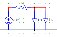
Vdc = 50 V
Cut-in voltage for D1 = 0.2 V
Cut-in voltage for D2 = 0.6 V
R = 5KΩ
Current through D1 & D2 would be,
a) 5mA, 5mA
b) 10mA, 0
c) 0, 10mA
d) 9.98mA, 9.94mA
View Answer
Explanation: As the cut-in voltage for D1 is lesser than D2, D1 would start conducting first & S.C D2. Hence, only D1 conducts with I = 50/5000 A.
Sanfoundry Global Education & Learning Series – Power Electronics.
To practice all areas of Power Electronics, here is complete set of 1000+ Multiple Choice Questions and Answers.
If you find a mistake in question / option / answer, kindly take a screenshot and email to [email protected]
