In this tutorial, you will learn the concepts of error detection and error correction. This tutorial covers error detection and error correction methods along with their advantages, disadvantages, and working.
Contents:
- Error on Communication Channel
- Types of Errors
- Error Detection
- Parity Bit and Checksum
- Cyclic Redundancy Check (CRC)
- Error Correction
- Hamming Codes and Binary Convolution Codes
- Reed-Solomon and Low-Density Parity-Check
Error on Communication Channel
Certain methods are used to provide accuracy of data transmitted between devices on a communication channel. But still, the possibility of an error remains. When the sender sends data to the receiver over the communication channel, the data may be lost or corrupted, which generates an error.
- Several factors exist on the channel that are responsible for changing one or more bits of the message.
- Sometimes the error is not a problem on the network. For example, random errors can be tolerated when the sender and receiver communicate in audio or video format. But when sender and receiver transmit and receive data as text, we expect a high degree of accuracy over the network.
Types of Errors
When the sender sends the message in the form of bits from its physical layer to the physical layer of the recipient, some unexpected changes may occur due to interference. The original meaning and shape of the message may change due to interference, leading to errors. There are 2 types of errors as follows:
- Single-bit error
- Burst error
- Single-bit error: In a single-bit error, interference causes one bit of the message to change. For example, 0 to 1, or 1 to 0.
- Burst error: In a burst error, two or more bits of the message are changed during transmission. Also, in a burst error, the change of bits doesn’t need to be sequential. We can measure burst length by measuring from the first corrupted bit to the last corrupted bit, some bits in between may not be corrupted.
The below diagram explains the types of errors.
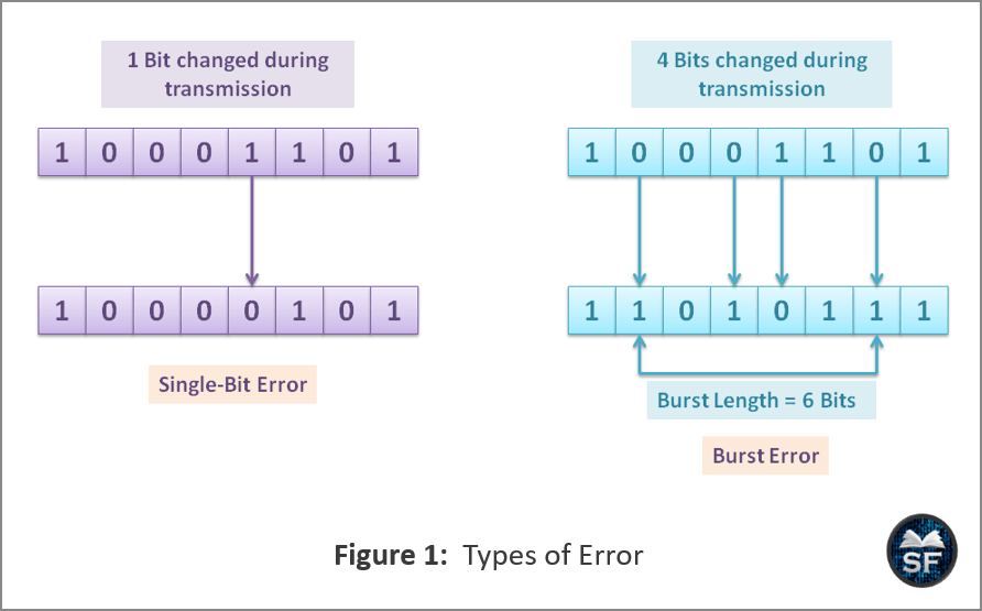
As you can see in the above diagram that in single-bit error, only one bit changes from 1 to 0 during transmission. In a burst error, 4 bits are changed during transmission, and the length of the burst becomes 6 bytes from the first corrupt bit to the last corrupt bit.
Error Detection
Error detection is used on the network to detect errors during transmission. Error detection codes are widely used on wireless or unguided networks, as wireless media have no physical shield, increasing the potential for errors such as data loss or corrupted data.
- Error detection is the situation when the received message does not match on the receiver side with the message sent by the sender.
- If we do not use error detection codes, it becomes very difficult to detect errors and resend data lost during transmission.
- In general, error detection and retransmission of data are usually more efficient than occasional error handling.
There are 3 types of error-detection codes we can use to detect errors in communication. They are as follows:
- Parity Bit
- Checksum
- Cyclic Redundancy Check (CRC)
Parity Bit and Checksum
Parity bits and checksums are methods of detecting errors during transmission to ensure that data is not lost or corrupted. In this section, we will discuss both methods one by one.
Parity Bit: In the Parity bit method, an additional bit is added to each word to make error detection possible on the communication channel. The parity bit has two values, either 0 or 1. Even Parity and odd parity are types of parity.
- Even Parity: The sender is sending the message as a stream of bits over the communication channel. After adding a parity bit (1 or 0) to the message, the number of 1’s becomes even then it is known as even-parity.
- Odd Parity: The sender is sending the message as a stream of bits over the communication channel. After adding a parity bit (1 or 0) to the message, the number of 1’s becomes odd then it is known as odd-parity.
The below diagram explains the parity bit method.
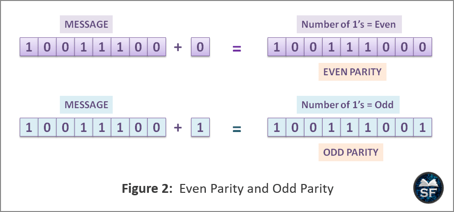
As you can see in the above diagram, the sender is transmitting 10011100 and, bit 0 is added to it, now 100111000 has an even number of 1’s so that it is even parity. If 1 is added to 10011100, it will make the odd parity message 100111001.
Checksum: The problem with the parity bit method is that it reliably detects only one-bit errors in the message. If the message contains a burst error, the parity bit method will not work. Therefore, the parity bit is only used when cables are challenging for error detection, as those cables have very low error rates. To solve the problem of the parity bit method, the checksum method is used.
- The checksum is the complement of the total of all the code-words. The Checksum is placed at the end of the message. The checksum method operates on words instead of bits.
The figure below explains the checksum method.
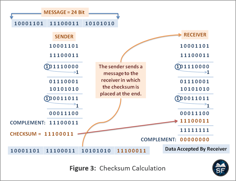
- As you can see in the above diagram that a 24-bit size message is divided into 3 smaller messages of 8 bits each. Now, the sender will sum all the 8 bits of the message and complement the result, which is the checksum.
- After the checksum is calculated, the sender will put the checksum in the message and send it to the receiver. Now, the receiver will sum up all the received messages of 8 bits.
- After that, the receiver will sum the result with the checksum, which was calculated by the sender. If the value of the sum’s complement becomes 0, the receiver confirms that there is no error in the message.
Cyclic Redundancy Check (CRC)
Cyclic redundancy check is another error detection technique, also known as polynomial code. In this method, redundancy bits are added to the original message before transmission so that if an error occurs midway through transmission, the receiver can detect it and inform the sender.
Redundant bits are decided by the divisor, and in CRC, the divisor is predetermined. To understand better, let’s look at an example of a CRC.
The below diagram explains the Cyclic Redundancy Check method.
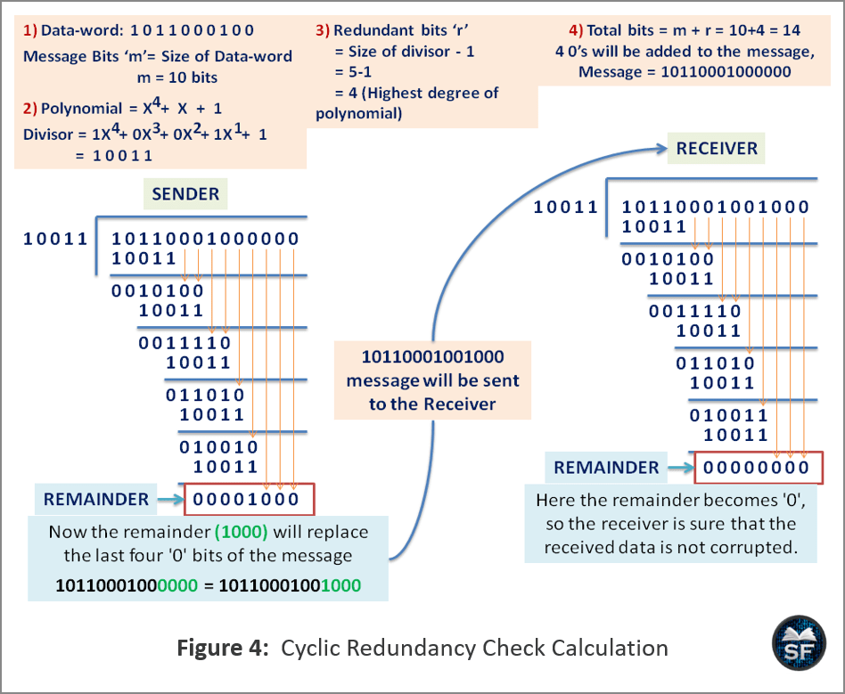
- In the above diagram, the size of the data-word 1011000100 and the divisor 10011 are 10 bits and 5 bits, respectively. Therefore, a total of redundant bits will be added to the data word, which is one smaller than the size of the divisor.
- So, you can see in the diagram that four 0’s have been added to the original message, which makes 10110001000000.
- After that, the CRC will be calculated on behalf of the sender and sent to the receiver. On the receiver side, the receiver will also calculate the CRC to detect whether an error has occurred or not.
- If the value of remainder becomes 0000, then the receiver ensures that the message received is not corrupted.
Error Correction
The error detection method is used to check whether an error has occurred in the data. Now it’s time to learn how we can fix the detected errors using error correction methods. The error correction method is used to find out the exact number of corrupted bits to correct.
Error correction can be done in two ways:
- Backward Error Correction
- Forward Error Correction
- Backward Error Correction: In simple words, the receiver sends an acknowledgment to the sender when corrupt data is received, and the sender retransmits the data to the receiver.
- Forward Error Correction: When the receiver receives data that contains errors, the receiver attempts to retrieve and correct the data using methods. The 4 main methods of Forward-Error correction are as follows:
- Hamming Codes
- Binary Convolution Codes
- Reed-Solomon Codes
- Low-Density Parity-Check Codes
Hamming Codes and Binary Convolution Codes
In each forward error correction method, the message has m bits size and r bits of a check or redundant bits are added, and the sum of message ‘m’ bits and redundant “r” bits is known as a block. The sender creates the block on his behalf using Hamming or Binary Convolution method and sends it to the receiver. The receiver will use the error correction methods on the message to correct the error.
Hamming Codes: The position of the bits changed in the block during transmission is called the Hamming distance. The Hamming distance is calculated on binary strings that have the same length.
The below diagram explains the Hamming Code.
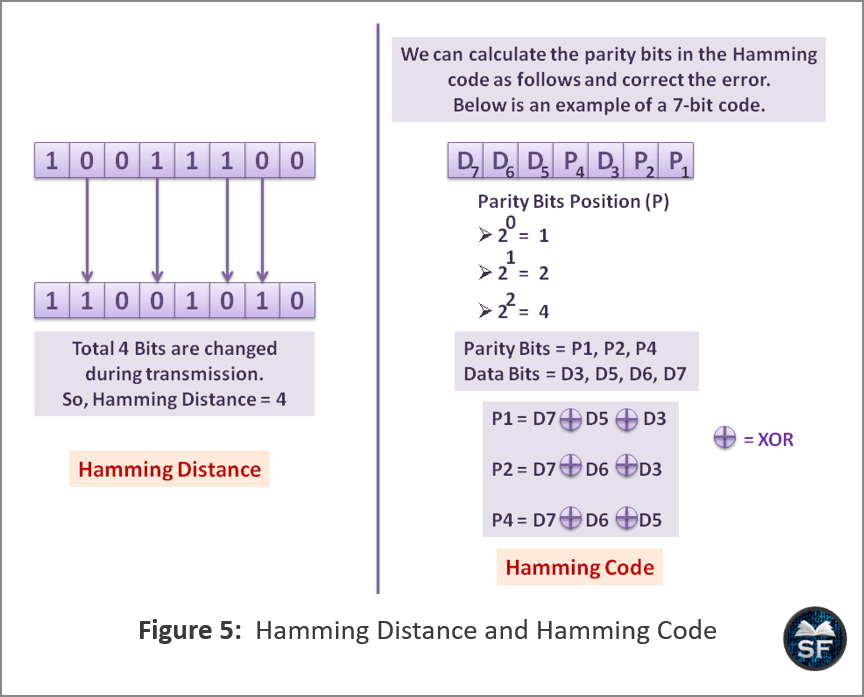
- As you can see in the above diagram, the hamming distance between two code-words is simply the number of bits that differ between two streams of bits. So, here the Hamming distance is ‘4’.
- When the receiver has calculated the Hamming distance, it will correct the error in the message using the Hamming code. In Hamming code, the position of the parity bits is in the power of 2.
- After the receiver detects the position of the parity bits, the receiver will perform an XOR operation to find the value of the parity bits and correct the error.
Binary convolution method: The second most useful method is binary convolution. In this method, the sender will encode the message and produce a sequence of output bits. Here, the output of the message depends on the current and previous bits.
- Convolution code is used in mobile phone systems, wireless communication, and satellite communication, etc.
- Convolution code has 3 states, input, internal, and output. Based on the input and the current state, the output will be calculated by performing the shifting process to the internal state.
- When the receiver decodes the convolution code by tracing the sequence of input bits sent by the sender that produces the output, the receiver will detect and correct errors.
Reed-Solomon and Low-Density Parity-Check
Reed-Solomon and low-density parity-check methods overcome the problems of Hamming codes and binary convolution codes. For example, the convolution code fails if there are too many errors in the received message, but we can overcome this problem using the Reed-Solomon method.
Reed-Solomon codes: Reed-Solomon codes are used with convolution codes. It contains additional redundant bits to provide reliable communication and a method for the receiver to correctly correct errors.
- In general, convolution codes are good at handling isolated bit errors, but if there are too many errors in the received message, the convolution code fails.
- Adding Reed-Solomon code to the convolution code protects against single and burst errors, which overcome the problem of convolution codes.
Low-Density Parity-Check (LDPC): Low-density parity checking codes are great for large block sizes because they have excellent error-correction capabilities.
- In this method, each output bit on the receiver side is made up of a fraction of the input bits, which leads to a matrix representation that has a low-density 1s code, hence known as a low-density parity-check.
- In today’s networks, most new protocols include LDPC codes.
- LDPC is part of the standard for digital video transmission, Ethernet with 10 Gbps speeds, power-line networks, and 802.11.
Key Points to Remember
Here is the list of key points we need to remember about “Error Detection and Error Correction”.
- Data loss or corruption that occurs during transmission on a channel is known as error. There are 2 types of errors:
- Single-bit error
- Burst error
- In a single-bit error, only one bit is changed during transmission, whereas in a burst error, several bits are changed./li>
- Error detection is the situation when the message received does not match the message sent by the sender.
- Three types of error-detection codes are used to detect errors in communication:
- Parity Bit
- Checksum
- Cyclic Redundancy Check (CRC)
- In the Parity bit method, an additional bit is added to each word to make error detection possible on the communication channel.
- The checksum is the complement of the total of all the code-words. The checksum is placed at the end of the message.
- Error correction can be done in two ways:
- Backward Error Correction
- Forward Error Correction
- There are four main methods of Forward-Error correction:
- Hamming Codes
- Binary Convolution Codes
- Reed-Solomon Codes
- Low-Density Parity-Check Codes
