This set of Structural Analysis Questions and Answers for Campus interviews focuses on “Analysis of Beams-4”.
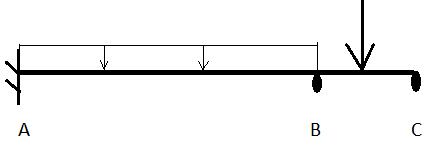
A is a fixed support, while B and C are roller supports. Uniformly distributed load of 2KN/m is acting on span AB. Load of 12 kN acts at a point between B and C. AB = 24m, BC = 8m. Load of 24KN acts at centre of BC.
All moment options are given in kN-M.
1. What will be the extra condition, which we will get if we conserve moment near joint B?
a) mBA + mCA = 0
b) mBA + mCB = 0
c) mBA + mBC = 0
d) mAB + mBC = 0
View Answer
Explanation: Just cut a small part near joint B and conserve moment around that joint.
2. Total how many equations will be generated?
a) 1
b) 2
c) 3
d) 4
View Answer
Explanation: Beam AB will give 2 equations, but ultimately beam BC will give only one equation.
3. What will be the value of rotation at point B after solving these equations?
a) 317/EI
b) -117/EI
c) -144/EI
d) 344/EI
View Answer
Explanation: Just use the above mentioned equation i.e. mBA + mBC = 0.
4. What will be the value of mAB, after solving these equations?
a) 108
b) 72
c) -72
d) -108
View Answer
Explanation: Just substitute the value of rotation at point B in 1st equation.
5. What will be the value of mBC, after solving these equations?
a) 108
b) 72
c) -72
d) -108
View Answer
Explanation: Just substitute the value of rotation at point B in 3rd equation.
6. What will be the value of mCB, after solving these equations?
a) 3.09
b) 1.54
c) 12.86
d) 0
View Answer
Explanation: It is already assumed that its value will be zero as we are considering support C as a pin.
7. What will be the value of mBA, after solving these equations?
a) 108
b) 72
c) -72
d) -108
View Answer
Explanation: It will be inverse of mBC as shown above.
8. What will be the shear at point A?
a) 25.5
b) 22.5
c) 15
d) -3
View Answer
Explanation: Just conserve moment in beam AB about point B.
9. What will be the shear at point C?
a) 25.5
b) 22.5
c) 15
d) -3
View Answer
Explanation: Just conserve moment in beam BC about point B.
10. What will be the support reaction at point B?
a) 25.5
b) 22.5
c) 15
d) 37.5
View Answer
Explanation: Find shear at point B in both beam AB and BC and then cut a small part near support B and conserve force in vertical direction.
11. There will be one point of discontinuity in the shear diagram of this question.
State whether the above statement is true or false.
a) true
b) false
View Answer
Explanation: This statement is true as in between the beam, one external support exerts some loading.
12. There will be one point of discontinuity in the bending moment diagram of this question.
State whether the above statement is true or false.
a) true
b) false
View Answer
Explanation: This statement is false as no external moment is applied in between the beam.
13. What will be the final moment at point C?
a) -108
b) 54.6
c) 0
d) 108
View Answer
Explanation: Point C is free end, so there won’t be any moment there.
14. What will be the final moment at point A?
a) -108
b) 54.6
c) 0
d) 108
View Answer
Explanation: It will be same as mAB, as no external moment is acting otherwise.
Sanfoundry Global Education & Learning Series – Structural Analysis.
To practice all areas of Structural Analysis for Campus Interviews, here is complete set of 1000+ Multiple Choice Questions and Answers.
If you find a mistake in question / option / answer, kindly take a screenshot and email to [email protected]
- Apply for Civil Engineering Internship
- Practice Civil Engineering MCQs
- Check Structural Analysis Books
- Check Civil Engineering Books
