This set of Software Engineering Multiple Choice Questions & Answers (MCQs) focuses on “Diagrams in UML – 1”.
1. Which of the following UML diagrams has a static view?
a) Collaboration
b) Use case
c) State chart
d) Activity
View Answer
Explanation: A use case diagrams captures only the functionality of the system whereas a dynamic model/view captures the functions as well as the action.
2. What type of core-relationship is represented by the symbol in the figure below?
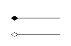
a) Aggregation
b) Dependency
c) Generalization
d) Association
View Answer
Explanation: None.
3. Which core element of UML is being shown in the figure?
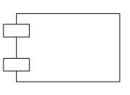
a) Node
b) Interface
c) Class
d) Component
View Answer
Explanation: The figure is self explanatory. A component is a modular, significant and replaceable part of the system that packages implementation and exposes a set of interfaces.
4. What type of relationship is represented by Shape class and Square ?
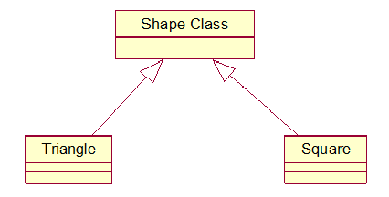
a) Realization
b) Generalization
c) Aggregation
d) Dependency
View Answer
Explanation: The generalization relationship is also known as the inheritance relationship. In the figure Square is the subclass of superclass shape.
5. Which diagram in UML shows a complete or partial view of the structure of a modeled system at a specific time?
a) Sequence Diagram
b) Collaboration Diagram
c) Class Diagram
d) Object Diagram
View Answer
Explanation: An object diagram focuses on some particular set of object instances and attributes, and the links between the instances. It is a static snapshot of a dynamic view of the system.
6. Interaction Diagram is a combined term for
a) Sequence Diagram + Collaboration Diagram
b) Activity Diagram + State Chart Diagram
c) Deployment Diagram + Collaboration Diagram
d) None of the mentioned
View Answer
Explanation: Interaction diagram are used to formalize the dynamic behavior of the system.
7. Structure diagrams emphasize the things that must be present in the system being modeled.
a) True
b) False
View Answer
Explanation: Since structure diagrams represent the structure they are used extensively in documenting the architecture of software systems
8. Which of the following diagram is time oriented?
a) Collaboration
b) Sequence
c) Activity
d) None of the mentioned
View Answer
Explanation: A sequence diagrams timeline along which tasks are completed.
Sanfoundry Global Education & Learning Series – Software Engineering.
If you find a mistake in question / option / answer, kindly take a screenshot and email to [email protected]
- Check Software Engineering Books
- Practice Information Technology MCQs
- Check Computer Science Books
- Practice BCA MCQs
- Practice Computer Science MCQs
