This set of Signals & Systems written test Questions & Answers focuses on “Fourier Series Analysis using Circuits”.
1. Given x (t) = [2 + e-3t] u (t). The final value of x(t) is ___________
a) 2
b) 3
c) e-3t
d) 0
View Answer
Explanation: Given x (t) = [2 + e-3t] u (t)
Applying final value theorem, we get, limt→∞ x(t)= lims→0 sX(s)
= lims→0 \(s[\frac{1}{s} + \frac{1}{s+3}]\)
= lims→0 \(\frac{2s+3}{s+3}\)
= 2.
2. The Fourier series of the given signal is _______________
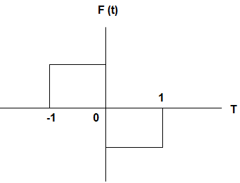
a) -4/π sin x
b) 4/π sin x
c) 4/π cos x
d) -4/π cos x
View Answer
Explanation: We know that the Fourier series is given by a0 + \(∑_{n=1}^∞\) (an cos nx + bn sin nx)
This can be also written as a0 + a1cos x + b1 sin x + a2 cos 2x + b2 sin 2x ……
Here, c0 = a0 = 0
So, cn = bn = \(2∫_0^t f(t).sinωt \,dt\)
∴ c1 = b1 = \(2∫_0^t sinωt \,dt\)
= \(– \frac{2}{ω} [cosωt]_0^t\)
= \(-\frac{2}{π}\)[-1-1] = 4/π
And a1 = \(2∫_0^t f(t).cosωt \,dt\)
= \(\frac{2}{ω}[sinωt]_0^t\)
= 0
So, the Fourier series can be written as 0 + 0.cos x + 4/π sin x
= 4/π sin x.
3. For the circuit given below, the effective inductance of the circuit across the terminal AB, is ___________
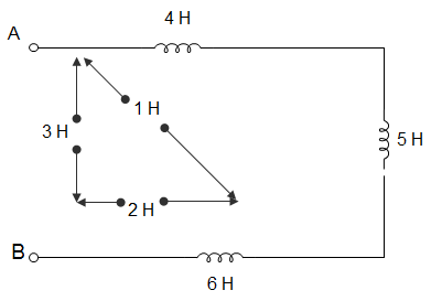
a) 9 H
b) 21 H
c) 11 H
d) 6 H
View Answer
Explanation: LEFF across AB = L1 + L2 + L3 – 2M12 – 2M13 + 2M23
= (4 + 5 + 6 – 2×1 – 2×3 + 2×2)
= (15 – 2 – 6 + 4)
= (15 – 8 + 4)
= (15 – 4)
= 11.
4. For the circuit given below, the inductance measured across the terminals 1 and 2 was 15 H with open terminals 3 and 4. It was 30 H when terminals 3 and 4 were short-circuited. Both the inductors are having inductances 2H. The coefficient of coupling is ______________
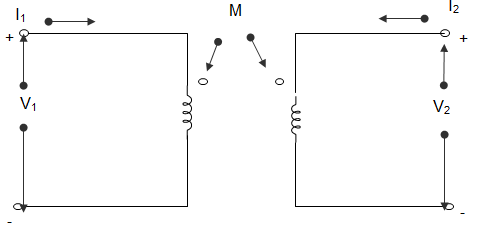
a) 1
b) 0.707
c) 0.5
d) Inderminate due to insufficient data
View Answer
Explanation: When 2 coils are connected in series, then effective inductance,
LEFF = L1 + L2 ± 2M
For this case, LEFF = L1 + L2 – 2M
However, L1 + L2 + 2M or L1 + L2 – 2M cannot be determined.
Hence, data is insufficient to calculate the value of coupling coefficient (k).
5. In the circuit given below, the resonant frequency is ________________
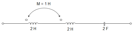
a) \(\frac{1}{2π\sqrt{3}}\) Hz
b) \(\frac{1}{4π\sqrt{3}}\) Hz
c) \(\frac{1}{4π\sqrt{2}}\) Hz
d) \(\frac{1}{π\sqrt{2}}\) Hz
View Answer
Explanation: LEFF = L1 + L2 + 2M
= 2 + 2 + 2 × 1
Or, LEFF = 6 H
At resonance, ωL = \(\frac{1}{ωC}\)
Or, ω = \(\frac{1}{\sqrt{L_{EFF} C}} = \frac{1}{\sqrt{12}}\)
Or, I = \(\frac{1}{4π\sqrt{3}}\) Hz.
6. Q meter operator is the principle of __________
a) Series resonance
b) Current resonance
c) Self-inductance
d) Eddy currents
View Answer
Explanation: We know that, Q = \(\frac{ωL}{R}\)
From the above relation, we can say that it works on series resonance.
7. The probability cumulative distribution function must be monotone as well as ___________
a) Increasing
b) Decreasing
c) Non-increasing
d) Non-decreasing
View Answer
Explanation: The probability cumulative distribution function increases to 1 monotonically and there after remains constant. Therefore we can say that the probability cumulative distribution function must be monotone as well as non-decreasing.
8. The impedance seen by the source in the circuit is given by __________
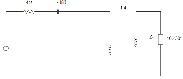
a) (0.54 + j0.313) Ω
b) (4 – j2) Ω
c) (4.54 – j1.69) Ω
d) (4 + j2) Ω
View Answer
Explanation: Z1 = 10∠30° × \((\frac{1}{4})^2\)
Z1 = (0.54 + j0.31) Ω
Total impedance= (4 – j2) + (0.56 + j0.31)
= (4.54 – j1.69) Ω.
9. In the circuit given below, the capacitor is initially having a charge of 10 C. 1 second after the switch is closed, the current in the circuit is ________
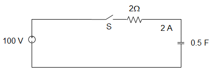
a) 14.7 A
b) 18.5 A
c) 40.0 A
d) 50.0 A
View Answer
Explanation: Using KVL, 100 = \(R\frac{dq}{dt} + \frac{q}{C}\)
100 C = RC\(\frac{dq}{dt}\) + q
Or, \(\int_{q_o}^q \frac{dq}{100C-q} = \frac{1}{RC} \int_0^t \,dt\)
100C – q = (100C – qo)e-t/RC
I = \(\frac{dq}{dt} = \frac{100C – q_o}{RC} e^{-1/1}\)
∴ e-t/RC = 40e-1 = 14.7 A.
10. Convolution is used to find ____________
a) Impulse of an LTI system
b) Frequency response of an LTI system
c) Time response of an LTI system
d) Phase response of an LTI system
View Answer
Explanation: We know that, the time response of an LTI system is given by
Y (n) = \(∑_{k=-∞}^∞ x(k)h(n-k)\)
This can also be written as y (n) = x (n) * h (n), which is the convolution of two systems. Therefore convolution is used to find the time response of an LTI system.
11. The Fourier transform of a rectangular function is ___________
a) Another rectangular pulse
b) Triangular pulse
c) Sinc function
d) Impulse
View Answer
Explanation: Substituting the square pulse function f (t) in the below equation as shown,
F (jω) = \(\int_{-∞}^∞ f(t) e^{jωt} \,dt\)
This gives us the Sinc function.
12. The property of Fourier Transform which states that the compression in time domain is equivalent to expansion in the frequency domain is ___________
a) Duality
b) Scaling
c) Time scaling
d) Frequency shifting
View Answer
Explanation: We know that the definition of Fourier Transform states that Fourier Transform is a function derived from a given function and representing it by a series of sinusoidal functions. The property of Fourier Transform which states that the compression in the time domain is equivalent to expansion in the frequency domain is Scaling can be found by putting the value of pulse function in the definition of Fourier Transform.
13. A coil of inductance 10 H, resistance 40 Ω is connected as shown in the figure. After the switch S has been in connection with point 1 for a very long time, it is moved to point 2 at t=0. For the value of R obtained, the time taken for 95 % of the stored energy dissipated is close to?
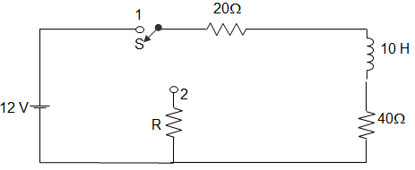
a) 0.10 s
b) 0.15 s
c) 0.50 s
d) 1.0 s
View Answer
Explanation: For source free circuit,
I (t) = Io \(e^{-\frac{R}{T} \,t}\)
∴ I (t) = 0.05 = 2 × \(e^{-\frac{60}{10} \,t}\)
Or, t = 0.61 ≈ 0.5 s.
14. The function which has its Fourier transform, Laplace transform, and Z transform unity is __________
a) Gaussian
b) Impulse
c) Sinc
d) Pulse
View Answer
Explanation: The definition of Fourier transform is \(\int_{-∞}^∞ f(x) e^{2πjxf} \,dx\)
The definition of Laplace transform is \(\int_0^∞ f(t) e^{-st} \,dt\)
The definition of Z-transform is \(∑_{n=-∞}^∞ x[n]z^{-n}\)
Substituting f (t) = δ (t) in the definitions of Fourier Laplace and Z-transform, we get the transforms in each case as 1. Hence an impulse function has unity Fourier Laplace and Z-transform.
15. N(t) = 2, 0≤t<4;
t2, t≥4;
The Laplace transform of M (t) is ___________
a) \(\frac{2}{s} – e^{-4s} (\frac{2}{s^3} – \frac{8}{s^2} – \frac{14}{s})\)
b) \(\frac{2}{s} + e^{-4s} (\frac{2}{s^3} – \frac{8}{s^2} – \frac{14}{s})\)
c) \(\frac{2}{s} – e^{-4s} (\frac{2}{s^3} + \frac{8}{s^2} + \frac{14}{s})\)
d) \(\frac{2}{s} + e^{-4s} (\frac{2}{s^3} + \frac{8}{s^2} + \frac{14}{s})\)
View Answer
Explanation: N (t) = 2 + u (t) (t2 – 2)
L {2 + u (t) (t2-2)} = \(\frac{2}{s}\) + L {u (t) (t2-2)}
= \(\frac{2}{s} + e^{-4s}\) L {(t+4)2 – 2}
= \(\frac{2}{s} + e^{-4s}\) L {t2 + 8t + 14}
= \(\frac{2}{s} + e^{-4s} (\frac{2}{s^3} + \frac{8}{s^2} + \frac{14}{s})\).
Sanfoundry Global Education & Learning Series – Signals & Systems.
To practice all written questions on Signals & Systems, here is complete set of 1000+ Multiple Choice Questions and Answers.
If you find a mistake in question / option / answer, kindly take a screenshot and email to [email protected]
