This set of Power Systems Questions and Answers for Freshers focuses on “Inductance of Composite Conductor Lines – 2”.
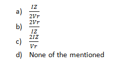
1. Based on the below given phasor diagram, the condition for the zero voltage regulation occurs at ______________
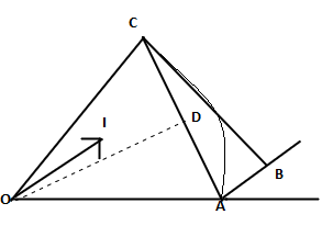
a) OC = OA
b) OC > OA
c) OC = OD
d) DC = AB
View Answer
Explanation: Zero VR occurs when both the emf and the load voltage are equal.
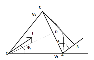
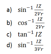
2. In the below given phasor diagram representation, the angle sine(AOD) for the condition of zero voltage regulation will be given by ___________
View Answer
Explanation: Geometrically sin(AOD) = AD/OA = (AC/2)/|Vr|
The below given phasor diagram is for question number 3, 4 and 5

3. In the phasor diagram representation, the angle (AOD) for the condition of zero voltage regulation will be given by _______________
View Answer
Explanation: It is geometrically sin(AOD) = AD/OA = (AC/2)/|Vr|
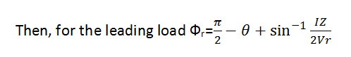
4. In the phasor diagram, the angle Фr such that zero voltage regulation occurs at the receiving end of a transmission line for a leading load, is given as __________
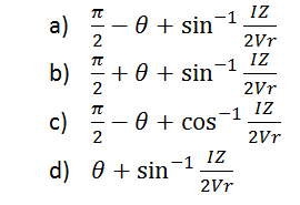
View Answer
Explanation: It is geometrically sin(AOD) = AD/OA = (AC/2)/|Vr|.
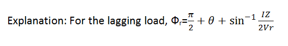
5. In the phasor diagram, the angle Фr such that zero voltage regulation occurs at the receiving end of a transmission line for a lagging load, is given as ___________
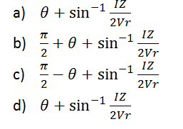
View Answer
6. For a transmission line under study of failure analysis, it is observed that the current at the receiving end is same as that of the sending end, then what can be concluded about the nature of the transmission line?
a) It is short TL
b) It is medium TL
c) It is long TL
d) Current is always same at the receiving end and the sending end.
View Answer
Explanation: It is a short transmission line as the capacitance considered is zero and so the line charging current is also zero.
7. A single phase 50 hz, generator supplies an inductive load of 5 MW at a power factor of 0.8 lagging using OHTL over 20 km. The resistance and reactance are 0.39Ω and 3.96 Ω. The voltage at receiving station is maintained at 10 KV. The sending end voltage is ______
a) 11.68 kV
b) 7.62 kV
c) 14.4 kV
d) 12.2 kV
View Answer
Explanation: Current, I = 5000/(10*0.8)
=625 A
Vs = |Vr|+|I|*(RcosФr + XsinФr)
= 10000+625(0.39*0.8+3.96*0.6)
= 11.68kV.
8. When the frequency of the system is increased, the charging MVAR of a system will __________
a) increase
b) decrease
c) remain constant
d) cannot be said
View Answer
Explanation: Increasing the frequency decreases the reactance and thus charging current increases and so the MVAR.
9.Taking a case study for the long line under no load condition, the receiving end voltage is ____________
a) more than the sending-end voltage
b) less than the sending-end voltage
c) equal to the sending-end voltage
d) it will not be affected by the loading
View Answer
Explanation: Due to Ferranti effect, the voltage will be more at receiving end in a LTL.
10. While given receiving-end voltage for a long transmission line, the sending-end voltage is more than the actual is found out using _____________
a) Nominal-pi method
b) Nominal-T method
c) Load end capacitance method
d) Any of the mentioned
View Answer
Explanation: In the nominal pi method, the losses are minimum.
Sanfoundry Global Education & Learning Series – Power Systems.
To practice all areas of Power Systems for Freshers, here is complete set of 1000+ Multiple Choice Questions and Answers.
If you find a mistake in question / option / answer, kindly take a screenshot and email to [email protected]
- Check Power System Books
- Apply for Electrical & Electronics Engineering Internship
- Apply for Electrical Engineering Internship
- Check Electrical & Electronics Engineering Books
- Practice Electrical Engineering MCQs
