This set of Power Systems Multiple Choice Questions & Answers (MCQs) focuses on “Flux Linkages of an Isolated Current-Carrying Conductor”.
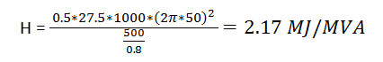
1. A 500 MW, 21 kV, 50 Hz three phase two pole alternator has 0.8 lagging p.f. with moment of inertia of 27.5×10³ kgm-2. The inertia constant H will be _______ MJ/MVA.
a) 2.17
b) 4.2
c) 2.82
d) 2.62
View Answer
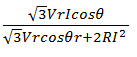
2. If the power system network is at Vs∠δ and receiving end voltage is Vr∠0 consisting of the impedance of TL as (R+j5)Ω. For maximum power transfer to the load, the most appropriate value of resistance R should be __________
a) 1.732
b) 3
c) 1.2
d) 0.33
View Answer
Explanation: For maximum power transfer, X=√3 R
3=√3 R
R=√3.
3. At a 33kV 50 Hz to a bus a load of 35 MW is connected. To improve the power factor to unity a synchronous phase modifier is connected taking 5 MW. If the SPM is represented as delta connected impedance, where in each phase we have capacitor connected parallel to resistance forming RC parallel network, then the value of this resistance is ___________
a) 653.4 Ω
b) 753.6 Ω
c) 280.4 Ω
d) 682 Ω
View Answer
Explanation: Reactive power fed by SPM = 35tan36.87 = 26.25 MVAR
Active power consumed by prime mover = 5 MW
5*106 = 3V2/R
R=3(33×1000)2/(5*106) = 653.4 Ω.
4. At a 33kV 50 Hz to a bus a load of 35 MW is connected. To improve the power factor to unity a synchronous phase modifier is connected taking 5 MW. If the SPM is represented as delta connected impedance, where in each phase we have capacitor connected parallel to resistance forming RC parallel network, then the value of this capacitance is __________
a) 25.57 μF
b) 76.2 μF
c) 32.2 μF
d) 24 μF
View Answer
Explanation: Q=3V2Cω
C= 25.57 μF.
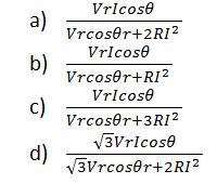
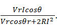
5.The transmission efficiency for a single phase line can be expressed as ____________
View Answer
Explanation: The efficiency of single phase is
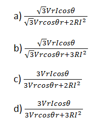
6. The transmission efficiency for a three phase line can be expressed as _________
View Answer
Explanation: The efficiency of three phase system is
7. If the flux linkages are varied sinusoid with current, then what can be concluded about the inductance?
a) Constant
b) Varying with the current
c) Linearly varying
d) Exponential change
View Answer
Explanation: Inductance = flux linkages/current.
8. The principle behind the influence of the power lines on the telephone lines is __________
a) Faraday’s laws
b) Mutual inductance
c) Self inductance
d) All of the mentioned
View Answer
Explanation: The concept of mutual inductance is the main reason for the interference between telephone lines and the power lines.
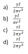
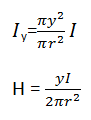
9. The magnetic flux intensity due to the current flowing inside the conductor is _________
View Answer
Explanation: Referring the ampere’s Law,
2πyH=Iy
Assuming uniform current density,
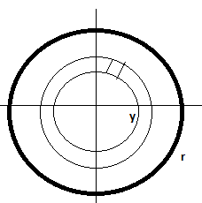
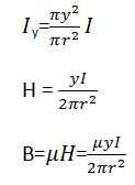
10. The flux density B, y meters from the centre of conductors in the following diagram, is _______
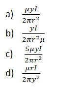
View Answer
Explanation: Referring the ampere’s Law,
2πyH=Iy
Assuming uniform current density,
11.The internal flux linking the single infinite conductor causes the inductance of ___________
a) 0.5 *10-7 H/m
b) 2 *10-7 H/m
c) 0.5 *10-7 ln(r) H/m
d) 2 *10-6 H/m
View Answer
Explanation: λint = I/2 x 10-7 Wb-T/m
L= λint/I = 0.5 *10-7 H/m.
12. The inductance of the conductor contributed by the flux between the point D outside at the distance d from conductor is _____________
a) 0.461 log(d/r) mH/km
b) 0.4 log(d/r) mH/km
c) 0.461 log(r/d) mH/km
d) 0.461 log(d/r) H/km
View Answer
Explanation: L= 0.461 log(d/r) mH/km.
Sanfoundry Global Education & Learning Series – Power Systems.
To practice all areas of Power Systems, here is complete set of 1000+ Multiple Choice Questions and Answers.
If you find a mistake in question / option / answer, kindly take a screenshot and email to [email protected]
- Practice Electrical & Electronics Engineering MCQs
- Check Electrical Engineering Books
- Check Power System Books
- Check Electrical & Electronics Engineering Books
- Practice Electrical Engineering MCQs
