This set of Linear Integrated Circuit Multiple Choice Questions & Answers (MCQs) focuses on “Voltage Shunt Feedback Amplifier”.
1. Voltage shunt feedback amplifier forms
a) A negative feedback
b) A positive feedback
c) Both positive and negative
d) None of the mentioned
View Answer
Explanation: A voltage shunt feedback amplifier forms a negative feedback because, any increase in the output signal results in a feedback signal into the inverting input causing a decrease in the output signal.
2. The value of feedback resistor and resistor connected in series with the input signal source are equal to 10kΩ and 3.3kΩ. Calculate the closed loop voltage gain?
a) -6.7
b) -33
c) -13.3
d) -3.33
View Answer
Explanation: Closed loop voltage gain, AF = -RF/R1 = -10kΩ/3.3kΩ = -3.33.
3. Write the formula for closed loop voltage gain of inverting amplifier with feedback using open loop voltage gain and gain of feedback circuit.
a) AF= A/(1+AB)
b) AF= -A/(1+AB)
c) AF= -B/(1+AB)
d) None of the mentioned
View Answer
Explanation: The closed loop voltage gain of the amplifier is AF= -Ak/(1+AB), where k is a voltage attenuation factor. In addition to phase inversion, AF is k times the closed loop gain of the non-inverting amplifier where k<1.
4. Voltage shunt feedback amplifiers are also called as
a) Non-inverting amplifier with feedback
b) Non-inverting amplifier without feedback
c) Inverting amplifier with feedback
d) Inverting amplifier without feedback
View Answer
Explanation: The input and output signal in voltage series feedback amplifier are 180o out of phase (or of opposite polarities). Due to this phase inversion, the configuration is also called as inverting amplifier with feedback.
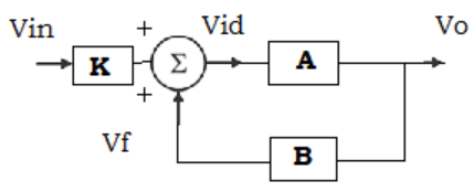
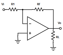
5. Find the block diagram representation for inverting amplifier with feedback
a)
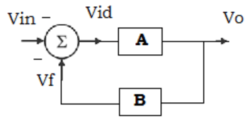
b)
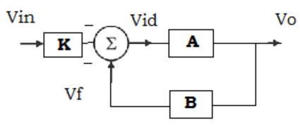
c)
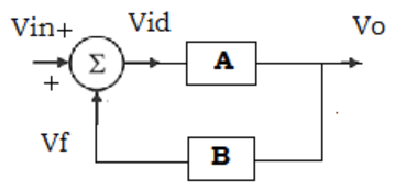
d)
View Answer
Explanation: The block diagram of non-inverting amplifier is identical to that of inverting amplifier except for the voltage attenuation factor or block. However, the major difference is that a voltage summing junction is being used as a model for what is actually a current summing.
6. The inverting input inverting of the voltage shunt feedback resistor is a commonly named as
a) Terminal ground
b) Virtual ground
c) Virtual input
d) Resistive input
View Answer
Explanation: Ideally, the difference between input voltages is zero. Therefore, the voltage at the inverting terminal is approximately equal to that of non-inverting terminal. In other words, the inverting terminal voltage is approximately at ground potential and it is said to be virtual ground.
7. Compute RIF for an inverting amplifier with feedback, where the value of input resistance of op-amp is 4.7kΩ.
a) 4.7kΩ
b) 9.4kΩ
c) 2.35kΩ
d) Data given is insufficient
View Answer
Explanation: In voltage shunt feedback amplifier, the input resistance with feedback is given as RIF = R1 (ideally).
8. Specification of op-amp 741c is given below:
A=200000; Ri=2MΩ; Ro=75Ω; Supply voltages= ±15v; output voltage swing =±13v; fo=5hz.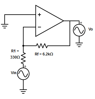
Compute the value of output resistance, bandwidth and closed loop voltage gain for the circuit shown.
a) ROF=8.6mΩ , fF= 53005hz and AF=-9.36
b) ROF=4.12mΩ , fF= 53005hz and AF=-11.78
c) ROF=7.1mΩ , fF = 53005hz and AF=-16.95
d) ROF=1.9mΩ , fF= 53005hz and AF=-10
View Answer
Explanation: Output resistance of the amplifier, ROF= Ro/(1+AB) =, where B= R1+RF = 330Ω/330Ω+6.2kΩ = 0.053.
=> ROF= ±75/(1+200000*0.053) = 53005hz.
Closed loop voltage gain, AF= -(A*K)/(1+AB), Where k= RF/(R1+F) = 6.2kΩ/(330Ω+6.2kΩ) = 0.949
=> AF = -(200000*0.949)/[1+(200000*0.0535)] = -16.95.
9. What is the break frequency of the op-amp?
a) fo = Unity Gain Bandwidth /closed loop voltage gain
b) fo = Unity Gain Bandwidth / open loop voltage gain
c) fo = Unity Gain Bandwidth /Gain of feedback circuit
d) All of the mentioned
View Answer
Explanation: The mentioned formula is the general break frequency of any operational amplifier.
10. The total voltage offset voltage with feedback (VooT) equation for inverting amplifier is
a) Same as that of non-inverting amplifier
b) k times the non-inverting amplifier, k-> voltage attenuation factor
c) Twice the equation of non-inverting amplifier
d) All of the mentioned
View Answer
Explanation: Voot equation for inverting amplifier is the same as that of the non-inverting amplifier because, when the input signal is reduced to zero, both inverting and non-inverting amplifier results in the same circuit.
11. Which among the following is not a special case of voltage shut feedback amplifier?
a) Voltage follower
b) Current to voltage connector
c) Inverter
d) None of the mentioned
View Answer
Explanation: A voltage follower is a special case of non-inverting amplifier ( or voltage series feedback amplifier) and it has a gain of unity.
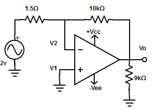
12. Compute the output voltage for the given circuit
a) -2.6v
b) -27.8v
c) -26.7v
d) -0.267v
View Answer
Explanation: The given circuit is a current to voltage converter. Since V1 =0v and V1= V2.
=> iin = Vin/R1 = 4/ 1.5kΩ =2.67mA.
The output voltage Vo = -iin*RF = -2.67mA*10kΩ = -26.7v.
13. At what condition an inverting amplifier works as an inverter
a) R1 = RF+ RL
b) RF =( R1*Vin)/RL
c) R1 = RF
d) R1 = Vo/(Vin*RL)
View Answer
Explanation: If R1 = RF, the inverting amplifier will work as an inverter.
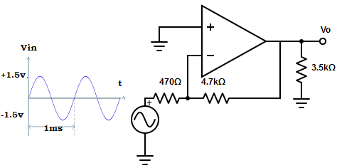
14. Determine the output waveform for the given input signal
a)
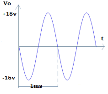
b)
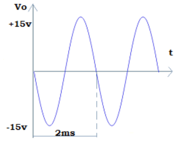
c)
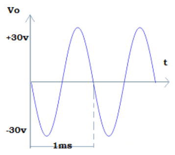
d)
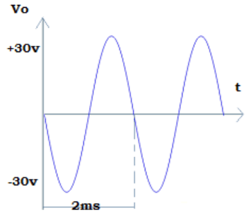
View Answer
Explanation: Given, Vin= 3Vpp sinewave at 1khz (Therefore F=1/T=1/ms =1khz)
=> iin= Vin/R1 = 3/ 470=6.4mA
=> Vo=- iin*RF=6.4mA*4.7kΩ = 30 Vpp sinewave at 1khz.
Sanfoundry Global Education & Learning Series – Linear Integrated Circuits.
To practice all areas of Linear Integrated Circuits, here is complete set of 1000+ Multiple Choice Questions and Answers.
If you find a mistake in question / option / answer, kindly take a screenshot and email to [email protected]
