logo
  • Home
  • Rank
  • Tests
  • About
  • Training
  • Programming
  • CS
  • IT
  • IS
  • ECE
  • EEE
  • EE
  • Civil
  • Mechanical
  • Chemical
  • Metallurgy
  • Instrumentation
  • Aeronautical
  • Aerospace
  • Biotechnology
  • Agriculture
  • MCA
  • BCA
  • Internship
  • Contact

Linear Integrated Circuits Multiple Choice Questions | MCQs | Quiz

Linear Integrated Circuits Interview Questions and Answers
Practice Linear Integrated Circuits questions and answers for interviews, campus placements, online tests, aptitude tests, quizzes and competitive exams.

Get Started

•   Differential Amplifier
•   Op-Amp Internal Circuit - 1
•   Op-Amp Internal Circuit - 2
•   Op-Amp Internal Circuit - 3
•   Op-Amp Internal Circuit - 4
•   Integrated Circuits - 1
•   Integrated Circuits - 2
•   IC Chip Size & Circuit
•   Basic Planar Process - 1
•   Basic Planar Process - 2
•   Basic Planar Process - 3
•   Active & Passive IC - 1
•   Active & Passive IC - 2
•   Active & Passive IC - 3
•   Thin Film Technology
•   FET Fabrication
•   IC Package Type - 1
•   IC Package Type - 2
•   Data Sheets Interpreting - 1
•   Data Sheets Interpreting - 2
•   Ideal Operational Amplifier
•   Open Loop Op-Amp
•   Feedback Configurations
•   Voltage Series Amplifier - 1
•   Voltage Series Amplifier - 2
•   Voltage Shunt Amplifier
•   Multiple Op-Amp - 1
•   Multiple Op-Amp - 2
•   Input Offset Voltage - 1
•   Input Offset Voltage - 2
•   Input Offset Voltage - 3
•   Input Bias Current
•   Input Offset Current
•   Thermal Drift
•   Offset Voltage Effect
•   Noise
•   Rejection Ratio
•   Frequency Response
•   Non-Compensating Op-Amp
•   Open-Loop Voltage Gain-1
•   Open-Loop Voltage Gain-2
•   Circuit Stability
•   Slew Rate - 1
•   Slew Rate - 2
•   DC & AC Amplifiers
•   AC Amplifiers
•   Peaking Amplifier
•   Averaging Amplifier - 1
•   Averaging Amplifier - 2
•   Instrumentation Amplifier - 1
•   Instrumentation Amplifier - 2
•   Instrumentation Amplifier - 3
•   Op-Amp Equivalent Circuit
•   Voltage-Current Converter-1
•   Voltage-Current Converter-2
•   Current-Voltage Converter
•   Input Impedance Circuit
•   Log & Antilog Amplifier
•   Multiplier & Divider - 1
•   Multiplier & Divider - 2
•   Integrator - 1
•   Integrator - 2
•   Differentiator
•   Active Filters - 1
•   Active Filters - 2
•   1st Order Butterworth Filter
•   2nd Order Butterworth Filter
•   Higher Order Filters
•   Band Pass Filters
•   All Pass Filters
•   Sine Wave Oscillator - 1
•   Sine Wave Oscillator - 2
•   Sine Wave Oscillator - 3
•   Sine Wave Oscillator - 4
•   Square Wave Generator
•   Sawtooth Wave Generator
•   Comparator
•   Schmitt Trigger
•   Precision Type Comparator
•   Basic DAC Techniques - 1
•   Basic DAC Techniques - 2
•   A to D Converter - 1
•   A to D Converter - 2
•   DAC / ADC Specification
•   Clippers & Clampers
•   Peak Detector & Sampling
•   Monostable Multivibrator
•   Astable Multivibrator
•   Phase-Locked Loops
•   Phase Detector
•   Controlled Oscillator
•   PLL Applications
•   IC Voltage Regulator
•   Switching Regulator
•   Monolithic Phase Loop
•   Power Amplifiers

Best Reference Books

Linear Integrated Circuits Books
« Prev Page
Next Page »

Linear Integrated Circuit Questions and Answers – Voltage Controlled Oscillator

Posted on August 27, 2017 by staff10

This set of Linear Integrated Circuit Multiple Choice Questions & Answers (MCQs) focuses on “Voltage Controlled Oscillator”.

1. Which device is used for diagnostic purposes and for recording?
a) Low pass filter
b) Monolithic PLL
c) Voltage Controlled Oscillator
d) None of the mentioned
View Answer

Answer: c
Explanation: A Voltage Controlled Oscillator (VCO) is used for converting low frequency signals such as EEGs, EKG into an audio frequency range. These audio signals can be transmitted over two way radio communication systems for diagnostic purposes or can be recorded on a magnetic tape for further reference.
advertisement

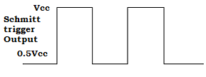
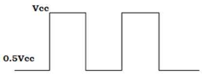
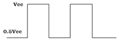
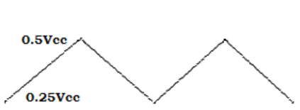
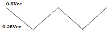
2. If the output of the Schmitt trigger is given below. Estimate the output at the pin 3 of VCO.
linear-integrated-circuit-mcqs-voltage-controlled-oscillator-q2
linear-integrated-circuit-mcqs-voltage-controlled-oscillator-q2a
View Answer

Answer: a
Explanation: In VCO, the output of Schmitt trigger is fed to the input of inverter. Therefore, the output at pin3 would be an inverted output. As the input is a square wave, the output obtained will be an inverted square wave.

3. Write the equation for time period of VCO?
a) (2×Vcc×CT)/i
b) (Vcc CT)/(2×i)
c) (Vcc×CT×i)/2
d) (2×Vcc)/(i×CT)
View Answer

Answer: b
Explanation: The time period of VCO is given as T=2×△t =(2×0.25×Vcc ×CT)/i =(0.5 V×cc×CT)/i = (Vcc×CT)/(2×i).

4. Determine the value of current flow in VCO, when the NE566 VCO external timing resistor RT =250Ω and the modulating input voltage Vc=3.25V.(Assume Vcc=+5v).
a) 3mA
b) 12mA
c) 7mA
d) 10mA
View Answer

Answer: c
Explanation: Current flowing in VCO, i =(Vcc– Vc)/ RT = (5V-3.25V)/250 = 1.75/250
=>i =7mA.

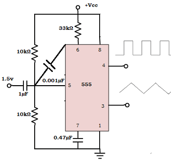
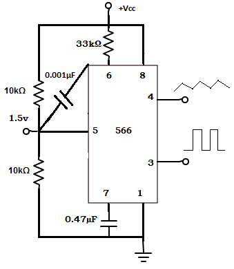
5. From the circuit given, find the value of output frequency?
linear-integrated-circuit-mcqs-voltage-controlled-oscillator-q5
a) 178.484 Hz
b) 104.84 Hz
c) 145.84 Hz
d) 110.88 Hz
View Answer

Answer: b
Explanation: Output frequency, fo =[2×(Vcc– Vc) ]/(CT×RT×Vcc )= [2x(8-1.5)]/(0.47µFx33kΩx8v) =13/0.124
=> fo=104.84 Hz.

6. The output frequency of the VCO can be changed by changing
a) External tuning resistor
b) External tuning capacitor
c) Modulating input voltage
d) All of the mentioned
View Answer

Answer: d
Explanation: The output frequency of VCO, fo = [2×(Vcc– Vc)]/(CT×RT×Vcc).
From the equation, it is clear that the fo is inversely proportional to CT & RT and directly proportional to Vc.Therefore, the output frequency can be changed by changing either voltage control, CT or RT.
advertisement

7. Calculate the value of external timing capacitor, if no modulating input signal is applied to VCO. Consider fo=25 kHz and RT=5 kΩ.
a) 6nF
b) 100µF
c) 2nF
d) 10nF
View Answer

Answer: c
Explanation: When modulating input signal is not applied to VCO, the output frequency becomes fo=1/(4×RT×CT)
=> CT =1/(4×RT×fo) =1/(4×5kΩ×25kHz) = 2×10-9 =2nF.

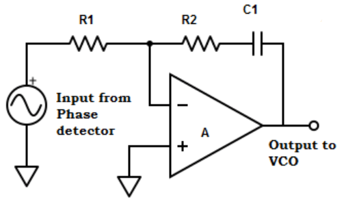
8. What is the advantage of using filter?
a) High noise immunity
b) Reduce the bandwidth of PLL
c) Provides dynamic range of frequencies
d) None of the mentioned
View Answer

Answer: a
Explanation: The charge on the filter capacitor gives a short time memory to the PLL. So, even if the signal becomes less than the noise for a few cycles, the dc voltage on the capacitor continues to shift the frequency of VCO, till it picks up the signal again. This produces high noise immunity.

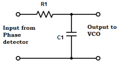
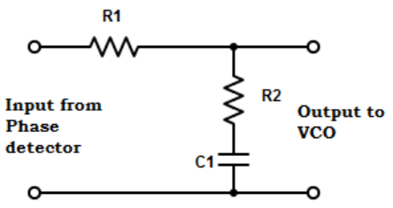
9. Which filter is used in VCO?
linear-integrated-circuit-mcqs-voltage-controlled-oscillator-q9
View Answer

Answer: d
Explanation: The loop filter used in the VCO can be one of the three types of filter shown above.

10. Choose the VCO for attaining higher output frequency.
a) NE566
b) SE566
c) MC4024
d) All of the mentioned
View Answer

Answer: c
Explanation: MC4024 is used for attaining high output frequency, because the maximum output frequency of NE566 and SE566 is 500kHz.

11. Voltage to frequency conversion factor for VCO is
a) Kv = △Vc/ △fo
b) Kv = △fo/△Vc
c) Kv = △fo × △Vc
d) Kv = 1/(△fo×△Vc)
View Answer

Answer: b
Explanation: The voltage to frequency conversion factor is defined as the change in frequency to the change in modulating input voltage.
=> Kv=△fo/△Vc.

12. Calculate the voltage to frequency conversion factor, where fo=155Hz and Vcc=10V.
a) 130
b) 124
c) 134
d) 116
View Answer

Answer: b
Explanation: The voltage to frequency conversion factor, Kv = △fo/△Vcc= 8×fo/Vcc = (8×155)/10=124.
advertisement

13. Find the equation for change in frequency of VCO?
a) △fo = (2×△Vc)/(RT×CT×Vcc)
b) △fo = △Vc/(4×RT×CT×Vcc)
c) △fo = △Vc/(2×RT×CT×Vcc)
d) △fo = (4×△Vc)/(RT×CT×Vcc)
View Answer

Answer: a
Explanation: The original output frequency, fo =2×[Vcc-Vc+△Vc]/[RT×CT×Vcc].
The new frequency f1 =2×[Vcc-Vc]/[RT×CT×Vcc].
Change in frequency, △fo= fo– f1 = 2×[Vcc-Vc+△Vc]/[RT×CT×Vcc]-{2×[Vcc-Vc]/[ RT×CT×Vcc] => △fo = (2×△Vc)/(RT×CT×Vcc).

14. Using the given specifications, determine the voltage to frequency conversion factor.
linear-integrated-circuit-mcqs-voltage-controlled-oscillator-q14
a) 8.32
b) 8.90
c) 8.51
d) 8.75
View Answer

Answer: c
Explanation: △fo = 2×△Vc/(RT×CT×Vcc)
=>△Vc= (△fo×RT×CT×Vcc)/2 = (4.7µFx10kΩx5x112)/2 = 13.16V.
Kv= △fo/ △Vc = 112Hz/13.16V
=>Kv=8.51.

Sanfoundry Global Education & Learning Series – Linear Integrated Circuits.

To practice all areas of Linear Integrated Circuits, here is complete set of 1000+ Multiple Choice Questions and Answers.

« Prev Page - Linear Integrated Circuit Questions and Answers – Phase Detector / Comparator
» Next Page - Linear Integrated Circuit Questions and Answers – PLL Applications

« Linear Integrated Circuit Questions and Answers – Phase Detector / Comparator
Linear Integrated Circuit Questions and Answers – PLL Applications »
advertisement

Deep Dive @ Sanfoundry:

  1. Instrumentation Transducers Questions and Answers
  2. Analog Circuits Questions and Answers
  3. Electrical Engineering Questions and Answers
  4. Optical Communications Questions and Answers
  5. Electrical Machines Questions and Answers
  6. Network Theory Questions and Answers
  7. Electronic Devices and Circuits Questions and Answers
  8. Digital Signal Processing Questions and Answers
  9. Linear Integrated Circuits Questions and Answers
  10. Linear Integrated Circuit Questions and Answers – Input Offset Current and Total Output Offset Voltage
Manish Bhojasia, a technology veteran with 20+ years @ Cisco & Wipro, is Founder and CTO at Sanfoundry. He is Linux Kernel Developer and SAN Architect and is passionate about competency developments in these areas. He lives in Bangalore and delivers focused training sessions to IT professionals in Linux Kernel, Linux Debugging, Linux Device Drivers, Linux Networking, Linux Storage & Cluster Administration, Advanced C Programming, SAN Storage Technologies, SCSI Internals and Storage Protocols such as iSCSI & Fiber Channel. Stay connected with him below:
LinkedIn | Facebook | Twitter | Google+

Best Careers

Developer Tracks
SAN Developer
Linux Kernel Developer
Linux Driver Developer
Linux Network Developer

Live Training Photos
Mentoring
Software Productivity
GDB Assignment
Sanfoundry is No. 1 choice for Deep Hands-ON Trainings in SAN, Linux & C, Kernel Programming. Our Founder has trained employees of almost all Top Companies in India such as VMware, Citrix, Oracle, Motorola, Ericsson, Aricent, HP, Intuit, Microsoft, Cisco, SAP Labs, Siemens, Symantec, Redhat, Chelsio, Cavium, ST-Micro, Samsung, LG-Soft, Wipro, TCS, HCL, IBM, Accenture, HSBC, Mphasis, Tata-Elxsi, Tata VSNL, Mindtree, Cognizant and Startups.

Best Trainings

SAN I - Technology
SAN II - Admin
Linux Fundamentals
Advanced C Training
Linux-C Debugging
System Programming
Network Programming
Linux Threads
Kernel Programming
Kernel Debugging
Linux Device Drivers

Best Reference Books

Computer Science Books
Algorithm & Programming Books
Electronics Engineering Books
Electrical Engineering Books
Chemical Engineering Books
Civil Engineering Books
Mechanical Engineering Books
Industrial Engineering Books
Instrumentation Engg Books
Metallurgical Engineering Books
All Stream Best Books

Questions and Answers

1000 C Questions & Answers
1000 C++ Questions & Answers
1000 C# Questions & Answers
1000 Java Questions & Answers
1000 Linux Questions & Answers
1000 Python Questions
1000 PHP Questions & Answers
1000 Hadoop Questions
Cloud Computing Questions
Computer Science Questions
All Stream Questions & Answers

India Internships

Computer Science Internships
Instrumentation Internships
Electronics Internships
Electrical Internships
Mechanical Internships
Industrial Internships
Systems Internships
Chemical Internships
Civil Internships
IT Internships
All Stream Internships

About Sanfoundry

About Us
Copyright
Terms
Privacy Policy
Jobs
Bangalore Training
Online Training
Developers Track
Mentoring Sessions
Contact Us
Sitemap
© 2011 Sanfoundry. All Rights Reserved.