This set of Linear Integrated Circuit Multiple Choice Questions & Answers (MCQs) focuses on “Second Order Low Pass Butterworth Filter”.
1. How can a first order low pass filter can be converted into second order low pass filter
a) By adding LC network
b) By adding RC network
c) By adding RC || LC network
d) None of the mentioned
View Answer
Explanation: The addition of RC network makes the stop band response having a 40dB/decade.
2. Consider the following specifications and calculate the high cut-off frequency for the circuit given?
a) 95Hz
b) 48Hz
c) 14Hz
d) 33Hz
View Answer
Explanation: The high cut-off frequency, fH= 1/[2 π√(R2 ×R3× C2× C3)] = 1/[2π√(33kΩ×15kΩ×0.47µF×0.1µF)]= 1/[2π× 4.82×(10-3)]= 33Hz.
3. Find the gain and phase angle of the second order low pass filter?
Where pass band gain of the filter is 5, frequency and the high cut-off frequency of the filter are 3000Hz and 1kHz.
a) None of the mentioned
b) Gain magnitude = -1.03dB , φ =63.32o
c) Gain magnitude = -5.19dB , φ =71.56o
d) Gain magnitude = -4.94dB , φ =90o
View Answer
Explanation: The gain of the second order low pass filter, [VO /Vin] =AF/ √ [1+(f/fh)2] =5/ √[1+(3000/1000)4] =5/9.055 =0.55.
=> [VO /Vin] = 20log(0.55) =-.519dB.
Phase angle of second order low pass filter is given as φ= tan-1(f/fH)
=> φ =71.56o.
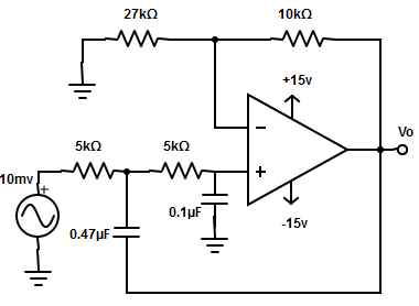
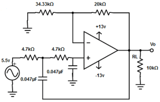
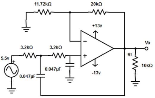
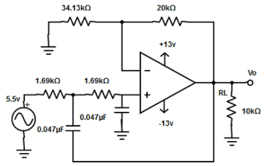
4. Design a second order low pass butterworth filter at a high cut-off frequency of 2.2kHz. Given RF=20kΩ and capacitor 0.047µF.
a)
b)
c)
d)
View Answer
Explanation: Given fH=21.2kHz, C2=C3 =0.047µF
R3 = 1/(2πfHC3 = 1/(2π×2.2kHz×0.047µF) =1/5.9032×10-4 =1.69kΩ.
=>R3 =R2=1.67kΩ
Since, RF=0.586R1
=> R1=RF/0.586 =20kΩ/0.586
R1 = 34.13kΩ.
5. A second order low pass filter is given an input frequency of 30kHz and produce a output having phase angle of 79o. Determine the pass band gain of the filter?
a) 11 dB
b) 89.11 dB
c) 46.78 dB
d) None of the mentioned
View Answer
Explanation: Phase angle of the filter, φ = tan-1(f/fH)
=> fh =f×tan(φ) =30kHz × tan(79
Therefore, the pass band gain AF = fH/0.707 = 154.34kHz/0.707
AF= 218.3 =20log(218.3)= 46.78dB.
6. The pass band voltage gain of a second order low pass butterworth filter is
a) 1.586
b) 8.32
c) 0.586
d) 0.707
View Answer
Explanation: Second order low pass filter has a pass band voltage gain equal to 1.586 because of equal resistor and capacitor values. This gain is necessary to guarantee butterworth response.
7. Arrange the series of step involved in designing a filter for first order low pass filter
Step 1: Select a value of C less than or equal to 1µF
Step 2: Choose a value of high cut-off frequency fH
Step 3: Select a value of R1C and RF depending on the desired pass band gain
Step 4: Calculate the value of R
a) Steps- 2->4->3->1
b) Steps- 4->1->3->2
c) Steps- 2->1->4->3
d) Steps- 1->3->4->2
View Answer
Explanation: The mentioned option is the sequence of steps followed for designing a low pass filter.
8. Frequency scaling is done using
a) Standard capacitor
b) Varying capacitor
c) Standard resistance
d) None of the mentioned
View Answer
Explanation: In frequency scaling standard capacitors are chosen, because for non standard value of resistor, a potentiometer is used.
Sanfoundry Global Education & Learning Series – Linear Integrated Circuits.
To practice all areas of Linear Integrated Circuits, here is complete set of 1000+ Multiple Choice Questions and Answers.
If you find a mistake in question / option / answer, kindly take a screenshot and email to [email protected]
