This set of Linear Integrated Circuit Multiple Choice Questions & Answers (MCQs) focuses on “Integrator – 2″.
1. Find the range of frequency between which the circuit act as integrator?
a) [1/(2πRFCF)]– (2πR1CF)
b) (2πRFCF) – [1/(2πR1CF)].
c) [1/(2πRFCF)]- [1/(2πR1CF)].
d) None of the mentioned
View Answer
Explanation:
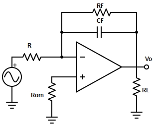
For a practical integrator, the gain limiting frequency is fa= 1/(2πRF CF). After fa, the gain decreases at a rate 20db/decade and reaches 0db. The frequency at which gain is 0db is fb= 1/(2π RF×CF). So, the circuit act as integrator between fa and fb.
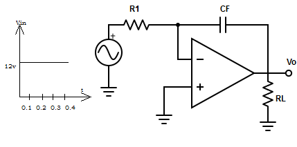
2. What will be the output voltage waveform for the circuit, R1×CF=1s and input is a step voltage. Assume that the op-amp is initially nulled.
a) Triangular function
b) Unit step function
c) Ramp function
d) Square function
View Answer
Explanation: Input voltage Vin = 1.2v for 0≤t≤0.4ms. The output voltage at t=0.4ms is
Vo = (1/R×CF)×t∫0 Vindt+C =-(1/1) × 0.4∫01.2 dt
=> Vo =-[0.1∫01.2 dt + 0.2∫0.11.2 dt + 0.3∫0.21.2 dt + 0.4∫0.31.2 dt ] = -(1.2+1.2+1.2+1.2) = -4.8v
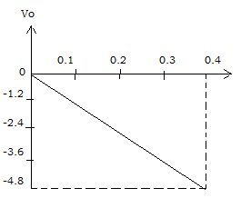
Therefore, the output voltage waveform is a ramp function.
3. Find R1 and RF in the lossy integrator so that the peak gain and the gain down from its peak is 40db to 6db. Assume ω=20,000 rad/s and capacitance = 0.47µF.
a) R1 = 10.6Ω, RF = 106Ω
b) R1 = 21.2Ω, RF = 212.6Ω
c) R1 = 42.4Ω, RF = 424Ω
d) R1 = 29.8Ω, RF = 298Ω
View Answer
Explanation: The gain of the lossy integration is A=(RF/ R1)/√[1+(ωRFCF)]2
=> A(db) = 20log{(RF/R1)/√[1+(ωRFCF)]2}
=> 40db = 20log×[(RF/R1)/√1
=> R1 = RF/20.
At ω=20000rad/s, the gain is down by 6db from its peak of 20db and thus is 14db. The gain at 14db => 14db= 20log ×{[ (RF/ RF/20)] / [√(1+(200000×0.47×10-6×RF)2]}
=> 20log[1+(9.4×10⁻³×RF)2] = 20-14
=> RF = √3/9.4×10-3 = 212.26Ω and R1 = 212.26Ω/10 = 21.2Ω.
4. Why a resistor is shunted across the feedback capacitor in the practical integrator?
a) To reduce operating frequency
b) To enhance low frequency gain
c) To enhance error voltage
d) To reduce error voltage
View Answer
Explanation: The input current charging the feedback capacitor produces error voltage at the output of the integrator. Therefore, to reduce error voltages a resistor (RF) is connected across the feedback capacitor. Hence, RF minimizes the variation in the output voltage.
5. Find the application in which integrator is used?
a) All of the mentioned
b) Analog Computers
c) FM Detectors
d) AM detectors
View Answer
Explanation: The integrator is most commonly used in analog computers mainly for signal wave shaping.
6. At what condition the input signal of the integrator is integrated properly
a) T = RFCF
b) T ≤ RFCF
c) T ≥ RFCF
d) T ≠ RFCF
View Answer
Explanation: The input signal will be integrated properly, if the time period T of the signal is larger than or equal to RF×CF (Feedback resistor and capacitor).
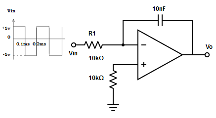
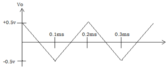
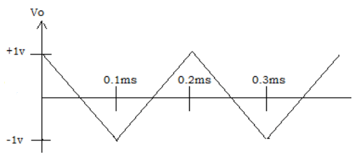
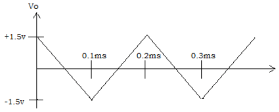
7. Find the output waveform for an input of 5kHz.
a)
b)
c)
d) None of the mentioned
View Answer
Explanation: The output voltage of integrator, Vo = (1/R1×CF)×t∫0 Vindt+C = -[(1/10kΩ×10nF) 0.1ms∫01dt ]= -(104×0.1×10-3) = -1v.
The input is constant amplitude of 2v from 0 to 0.1ms and from 0.1ms to 0.2ms. The output for each of these half periods will be ramp. Thus, the expected output is triangular wave.
8. What happens if the input frequency is kept lower than the frequency at which the gain is zero?
a) Circuit act like a perfect integrator
b) Circuit act like an inverting amplifier
c) Circuit act like a voltage follower
d) Circuit act like a differentiator
View Answer
Explanation: If the input frequency is lower that the lower frequency limit of the integrator (i.e. when gain = 0), there will be no integration results and the circuit act like a simple inverting amplifier.
9. Match the correct frequency range for integration. (Where f –> Input frequency and fa –> Lower frequency limit of integration)
| 1.f << fa | i. Results in 50% accuracy in integration |
| 2.f = fa | ii. Results in 99% accuracy in integration |
| 3.f = 10fa | iii. No integration results |
a) 1-iii, 2-i, 3-ii
b) 1-i, 2-ii, 3-iii
c) 1-ii, 2-iii, 1-i
d) 1-iii, 2-ii, 3-i
View Answer
Explanation: The mentioned answer gives the exact ranges where the integration starts.
Sanfoundry Global Education & Learning Series – Linear Integrated Circuits.
To practice all areas of Linear Integrated Circuits, here is complete set of 1000+ Multiple Choice Questions and Answers.
If you find a mistake in question / option / answer, kindly take a screenshot and email to [email protected]
