This set of Linear Integrated Circuit Multiple Choice Questions & Answers (MCQs) focuses on “Frequency Response and Compensating Networks”.
1. Variation in the operating frequency of op-amp causes
a) Variation in gain amplifier
b) Variation in gain phase angle
c) Variation in gain amplitude and its phase angle
d) None of the mentioned
View Answer
Explanation: The gain of the op-amp is a function of frequency. It will have a specific magnitude as well as a phase angle.
2. A graph of the magnitude of the gain versus frequency is called
a) Break frequency
b) Frequency response plot
c) Frequency stability plot
d) Transient response plot
View Answer
Explanation: A frequency response plot is obtained by plotting the gain of the op-amp responding to different frequencies.
3. In the frequency response plot, the frequency is expressed in
a) Anti-logarithmic scale
b) Logarithmic scale
c) Linear scale
d) Exponential scale
View Answer
Explanation: To accommodate large frequency ranges the frequency is assigned to a logarithmic scale.
4. Why the gain magnitude in frequency response plot is expressed in decibels (dB)
a) To obtain gain > 105
b) To obtain gain < 105
c) To obtain gain = 0
d) To obtain gain = ∞
View Answer
Explanation: In frequency response plot, gain magnitude is assigned a linear scale and is expressed in decibels to accommodate very high gain ( ≅ of the order 105 or higher).
5. Which technique is used to determine the stability of op-amp?
a) Frequency response plot
b) Transient response plot
c) Bode plot
d) All of the mentioned
View Answer
Explanation: Although frequency response and bode plots indicate the effect of frequency variation on gain, the Bode plot is generally used for stability determination and network design.
6. How many types of plots can be obtained in the AC analysis of network using Bode plot?
a) Five
b) Four
c) Three
d) Two
View Answer
Explanation: Two types of plots can be obtained using Bode plot. They are magnitude versus frequency and phase angle versus frequency plots.
7. What happens when the operating frequency of an op-amp increase?
a) Gain of the amplifier decrease
b) Phase shift between output and input signal decrease
c) Gain and phase shift of amplifier decreases
d) None of the mentioned
View Answer
Explanation: When the operating frequency is increased the gain of the amplifier decrease. As it is linearly related to frequency, the phase shift is logarithmically related to frequency.
8. Which of the following causes change in gain and phase shift?
a) Internally integrated Resistor
b) Internally integrated inductors
c) Internally integrated Capacitor
d) All of the mentioned
View Answer
Explanation: The change in function of frequency is attributed to the internally integrated capacitor as well as stray capacitor. These capacitors are due to the physical characteristic of semiconductor device.
9. Which plot is not provide by the manufactures?
a) Magnitude plot
b) Phase angle plot
c) Frequency response plot
d) None of the mentioned
View Answer
Explanation: Phase angle plot are not generally provided because phase shift of later generation op-amp are less than 90o even at cross over frequency.
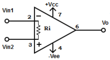
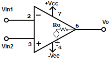
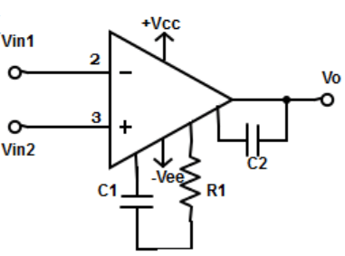
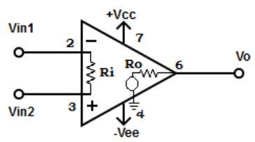
10. Find out the non-compensating op-amp from the given circuit
a)

b)

c)

d)

View Answer
Explanation: Non-compensating op-amp has external compensating components, that is , resistors and / or capacitors, are added at designated terminals. The mentioned op-amp has three compensating components: a resistor and two capacitors.
Sanfoundry Global Education & Learning Series – Linear Integrated Circuits.
To practice all areas of Linear Integrated Circuits, here is complete set of 1000+ Multiple Choice Questions and Answers.
If you find a mistake in question / option / answer, kindly take a screenshot and email to [email protected]
