This set of Linear Integrated Circuit Multiple Choice Questions & Answers (MCQs) focuses on “Differentiator”.
1. Differentiation amplifier produces
a) Output waveform as integration of input waveform
b) Input waveform as integration of output waveform
c) Output waveform as derivative of input waveform
d) Input waveform as derivative of output waveform
View Answer
Explanation: Differentiation amplifier or differentiator is a circuit that performs mathematical operation of differentiation and produce output waveform as a derivative of input waveform.
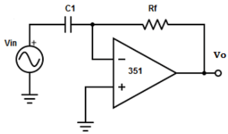
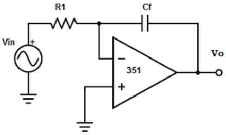
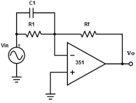
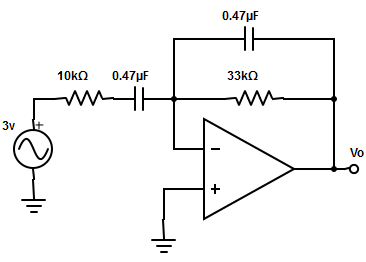
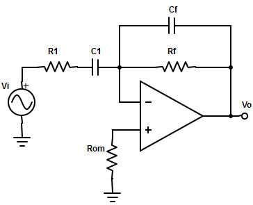
2. Find out the differentiator circuit from the given circuits?
a)
b)
c)
d)
View Answer
Explanation: The differentiator is constructed from basic inverting amplifier by replacing the input resistor R1 by replacing a capacitor C1.
3. Determine the output voltage of the differentiator?
a) VO = RF×C1×[dVin/dt].
b) VO = -RF×C1×[dVin/dt].
c) VO = RF×CF×[dVin/dt].
d) None of the mentioned
View Answer
Explanation: The output voltage is equal to the RF×C1 times the negative instantaneous rate of change of the input voltage Vin with time.
4. which factor makes the differentiator circuit unstable?
a) Output impedance
b) Input voltage
c) Noise
d) Gain
View Answer
Explanation: The gain of the differentiator circuit (RF / XC1) increases with increase in frequency at a rate of 20dB/decade. This makes the circuit unstable.
5. The increase in the input frequency of the differentiation amplifier to input impedance creates
a) Component noise
b) External noise
c) Low frequency noise
d) High frequency noise
View Answer
Explanation: The input impedance of the amplifier decreases with increase in frequency and make the circuit susceptible to high frequency noise such that noise can completely over ride differential output.
6. Calculate the gain limiting frequency for the circuit
a) 15.64Hz
b) 23.356Hz
c) 33.89Hz
d) None of the mentioned
View Answer
Explanation: The gain limiting frequency, fb= 1/(2π×R1×C1).
fb= 1/(2π×10kΩ×0.47µF)= 1/(2.9516×10-2) = 33.89Hz.
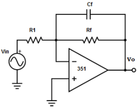
7. The stability and high frequency noise problem are corrected by
a) Adding feedback capacitor
b) Feedback capacitor and internal resistor
c) Feedback capacitor and feedback resistor
d) Internal capacitor and internal capacitor
View Answer
Explanation: The stability and high frequency noise problem are corrected by addition of two components to the differentiator: 1. Internal resistor in series with internal capacitor and
2. Feedback capacitor shunts with feedback resistor.
8. Select the order in which the frequency should be maintained to enhance the stability of differentiator? Where fa -> Frequency at which gain =0 ; fb -> Gain limit frequency ; fc -> Unity gain bandwidth.
a) fa < fb < fc
b) fa > fb > fc
c) fb < fc > fa
d) fb < fc < fa
View Answer
Explanation: The value of internal resistor and capacitor and feedback resistor and capacitor of the differentiator values should be selected such that fa < fb < fc to make the circuit more stable.
9. Which application use differentiator circuit?
a) None of the mentioned
b) FM modulators
c) Wave generators
d) Frequency Shift keying
View Answer
Explanation: The differentiators are used in FM modulator as a rate of change detector.
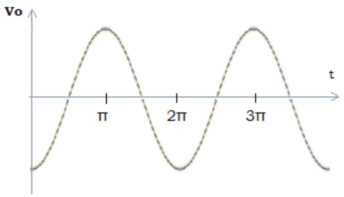
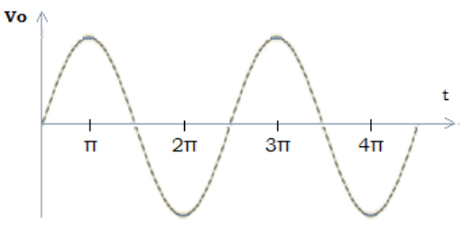
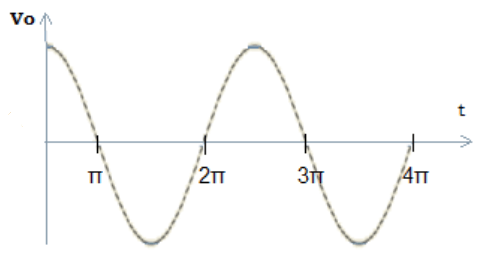
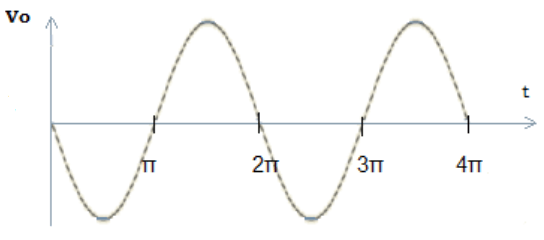
10. A sine wave of 1vpeak at 1000Hz is applied to a differentiator with the following specification: RF =1kΩ and C1=0.33µF, find the output waveform?
a)
b)
c)
d)
View Answer
Explanation: Given, Vin = Vp×sinωt = sin(2π×1000)t
The output of differentiator Vo = -RF×C1×(dVin/dt) =(1kΩ)×(0.33µF)×d[sin2π×1000t]/dt
= -3.3×10-4×2π×1000 ×[cos2π(1000)t] =-2.07×[cos2π(1000)t].
11. Choose the value of RF and C for a 5kHz input signal to obtain good differentiation.
a) RF = 1.6×10³Ω, C1 = 33×10-6F
b) RF = 1.6×10³Ω, C1 = 0.47×10⁻⁶F
c) RF = 1.6×10³Ω, C1 = 47×10-6F
d) RF = 1.6×10³ Ω, C1 = 10×10-6F
View Answer
Explanation: For a good differentiation, the time period of the input signal must be larger than or equal to RF C1 i.e. T ≥ RF×C1
Given f=5kHz , T=1/f = 1/5kHz = 2×10⁻⁴ –> Equ(1)
RF×C1 = 0.4µF×1.6kΩ =7.52×10⁻⁴ –> Equ(2)
Hence Equ(1) ≥ Equ(2).
12. Determine the transfer function for the practical differentiator
a) Vo(s) /V1(s) = -S×RF×C1/(1+R1×C1)2
b) Vo(s) /V1(s) = -S×RF×C1/(1+RF×C1)2
c) Vo(s) /V1(s) = -S×RF×C1/(1+R1×CF)2
d) None of the mentioned
View Answer
Explanation: The transfer function for the circuit,
Vo(s) /V1(s) =-S×RF×C1/{[1+(RF CF)]×[1+(S×R1×C1)]}.
In a practical differentiator, RFCF = R1C1
=> Vo(s) /V1(s) = -SRF×C1/(1+SRF×CF)2 or Vo(s) /V1’(s) = -S×RF×C1/(1+R1×C1)2.
Sanfoundry Global Education & Learning Series – Linear Integrated Circuits.
To practice all areas of Linear Integrated Circuits, here is complete set of 1000+ Multiple Choice Questions and Answers.
If you find a mistake in question / option / answer, kindly take a screenshot and email to [email protected]
