This set of Hydraulic Machines Multiple Choice Questions & Answers (MCQs) focuses on “Francis Turbine Velocity Diagrams”.
1. What is the water flow direction in the runner in a Francis turbine?
a) Axial and then tangential
b) Tangential and then axial
c) Radial and then axial
d) Axial and then radial
View Answer
Explanation: Francis turbine is radial flow reaction turbine. Though the water enters the turbine tangentially, it enters the runner radially inward and flows outward along the axis of the runner.
2. Which of the following is true in case of flow of water before it enters the runner of a Francis Turbine?
a) Available head is entirely converted to velocity head
b) Available head is entire converted to pressure head
c) Available head is neither converted to pressure head nor velocity head
d) Available head is partly converted to pressure head and partly to velocity head
View Answer
Explanation: Since Francis Turbine is a reaction turbine, part of the available head is converted to velocity head. It is not entirely converted to velocity head. The rest of the available head is converted into pressure head.
3. Why does the cross sectional area of the Spiral casing gradually decrease along the circumference of the Francis turbine from the entrance to the tip?
a) To ensure constant velocity of water during runner entry
b) To prevent loss of efficiency of the turbine due to impulsive forces caused by extra area
c) To prevent leakage from the turbine
d) To reduce material costs in order to make the turbine more economical
View Answer
Explanation: The primary purpose of the gradual decrease in area is so that the runner sees constant velocity of water at each point of entry. Absence of this may lead to inefficiency. The spiral casing is used to prevent leakage from the turbine but the gradual decrease in area is not for that reason.
4. Which of the following profiles are used for guide vanes to ensure smooth flow without separation?
a) Rectangular
b) Bent Rectangular
c) Elliptical
d) Aerofoil
View Answer
Explanation: Smooth flow and flow without separation (eddiless flow) can be ensured when the cross sectional profile of the guide vanes are aerofoil in nature. Aerofoil shape is used in airplane wings to ensure smooth flow too. Rectangular profiles are not effective in guiding the water into the runner. Elliptical profiles will cause more drag, finally ending up with turbine inefficiency.
5. In which of the following type of runners the velocity of whirl at inlet is greater than the blade velocity?
a) Such a case is practically impossible
b) Slow Runner
c) Medium Runner
d) Fast Runner
View Answer
Explanation: Considering the velocity diagram of Francis turbine at the inlet for a slow runner, we notice that the whirl velocity exceeds the blade velocity along the same direction. They are equal in case of a medium runner.
6. Which of the following runner types will have the highest vane angle at inlet (β1 value)?
a) Slow Runner
b) Medium Runner
c) Fast Runner
d) Vane angle is defined only for Kaplan Turbines and not Francis turbines
View Answer
Explanation: Considering the velocity diagram of Francis turbine at the inlet for a fast runner, vane angle is an obtuse angle. Whereas, it is right angle for medium runner and an acute angle for a slow runner.
7. In case of a Medium runner, tan (α1) CANNOT be given by (α1 = Guide vane angle at inlet)?
a) Vf1 / Vw1
b) Vr1 / Vw1
c) Vr1 / u1
d) Vw1 / u1
View Answer
Explanation: In medium runner, Vf1 = Vr1 & Vw1 = u1. Vw1 and u1 are along the same direction, hence that cannot be written as tan (α1).
8. In the velocity diagrams for Francis turbine, which of the following velocity directions is along the blade curvature?
a) Vr1
b) Vw1
c) V1
d) u1
View Answer
Explanation: Vr1 is the relative velocity of the water flow as seen from the blade. Thus, relative velocity is along the direction of the curvature of the blade.
9. In the figure shown below,which of the following angles replace the question mark?
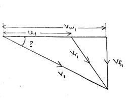
a) Guide vane angle at inlet
b) Blade angle at inlet
c) Vane angle at inlet
d) Blade angle at outlet
View Answer
Explanation: The angle between V1 and the blade velocity u1 is α1, which is the guide vane angle at the inlet.
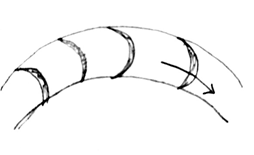
10. In the figure shown below, which of the following type of runners has the blade curvature as shown in the above figure (The arrow denotes direction of blade motion)?
a) Information insufficient to determine
b) Slow Runner
c) Medium Runner
d) Fast Runner
View Answer
Explanation: Fast runners have forward curved blades, where slow runners have backward curved blades. The blades shown in the figure are backward curved blades of a runner, which are used for slow runners.
Sanfoundry Global Education & Learning Series – Hydraulic Machines.
To practice all areas of Hydraulic Machines, here is complete set of 1000+ Multiple Choice Questions and Answers.
If you find a mistake in question / option / answer, kindly take a screenshot and email to [email protected]
- Apply for Mechanical Engineering Internship
- Check Hydraulic Machines Books
- Apply for Aerospace Engineering Internship
- Practice Mechanical Engineering MCQs
- Practice Aerospace Engineering MCQs
