This set of Heat Transfer Operations Multiple Choice Questions & Answers (MCQs) focuses on “HT Equipment – Shell and Tube Heat Exchangers”.
1. Shell and Tube Heat Exchangers are not commonly used in industries because of their inability to handle high pressure and temperature.
a) True
b) False
View Answer
Explanation: The above statement is wrong as shell and tube HE is the most common type of HE in industries due to the flexibility it provides to the user in terms of choice of operating pressure and temperature.
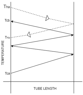
2. Which type of Shell and tube heat exchanger does the below temperature plot correctly represent?
a) Single Pass Shell and Tube
b) 1-2 Shell and Tube
c) 2-4 Shell and Tube
d) 3-6 Shell and Tube
View Answer
Explanation: In the given plot, we can observe the temperature has three elbows, that means it takes three turns(4 tubes) while its temperature increases in the tube side while its shell side observes only one turn(2 sections). Hence we can easily infer from this that it is a 2-4 shell and tube HE.
3. Consider we have a 1-2 Shell and Tube Heat Exchanger with tube diameter 20mm and shell diameter 55mm, we have two fluids A&B, A is supply water and B is distilled water, we desire to have their flow rates as 15m3/s and 21m3/s respectively. Which fluid pass arrangement would be best suited for the HE?
a) Parallel flow with A in tube and B in the shell side
b) Counterflow with B in tube and A in the shell side
c) Counterflow with A in tube and B in the shell side
d) Parallel flow with B in tube and A in the shell side
View Answer
Explanation: When we are required to provide the best arrangement for a Shell and Tube HE, we consider keeping the fluid with fouling properties on the shell side, this helps to clean the fouling caused on the equipment for the longevity of the equipment and also reduce maintenance costs.
4. How many times do we have to calculate for Pressure drop in a Shell and Tube Heat Exchanger?
a) 1
b) 2
c) 3
d) 4
View Answer
Explanation: For a Shell and Tube HE, we have to calculate pressure drop twice, once for the tube to check whether the equipment can handle that pressure. Similarly, the second time for the shell side.
5. In an operation where we want to heat a stream of liquid by Steam, we have the option to use extended fins. Then which of the following is best suited?
a) Steam on the shell side with the fins on outer surface of the tube
b) Steam on the tube side with the fins on outer surface of the tube
c) Steam on the shell side with the fins on inner surface of the tube
d) Steam on the tube side with the fins on inner surface of the tube
View Answer
Explanation: We keep steam on the shell side to withstand high flow rate, high pressure and easy removal of condensate. It is usually preferred to keep the fins on the gas side to increase its heat transfer coefficient as the coefficient is usually low for gases.
6. What can we infer from the name 2-4 Shell and Tube Heat Exchanger?
a) Partition of the Shell into two and four passes of the tube
b) Partition of the Shell into two three passes of the tube
c) One Shell and Four pass of the tube
d) Partition of the Shell into three four passes of the tube
View Answer
Explanation: The diagram for a 2-4 Shell and Tube HE is as shown, we can observe that it has a partition in the shell side dividing it into two parts and four passes of the tube, two in one shell part and the rest in the other two.
7. When we want to heat a stream of liquid by Steam, we usually keep steam on the shell side and fluid in the tube.
a) True
b) False
View Answer
Explanation: It is best suited when we keep the steam on the shell side because it is easier and mechanically more feasible to remove condensate from the shell side as film condensation decreases the heat transfer coefficient.
8. When a fluid is used in a Shell and Tube heat exchanger, which one of the following is not true?
a) If the fluid is gas then the gas side heat transfer coefficient is the lowest
b) Extended fins are used on the shell side to increase the Heat Transfer coefficient
c) Baffles are provided only to work as fins
d) Fins increase necessary heat transfer area
View Answer
Explanation: Fins are generally used to increase the Heat transfer Area when the heat transfer coefficient on that fluid side is comparatively low. Hence as gases usually have lower heat transfer coefficients, fins are kept on this side. Also baffles are provided to give support to the tubes and increase the turbulence of the fluid in shell side.
9. Which of the following statements are incorrect about Baffles in a Shell and Tube HE?
a) Baffles provide mechanical support to the tubes and help them to be in position
b) Baffles streamline the motion of the fluid in Shell side and hence decreases the turbulence
c) The most common type of baffle is segmental baffles
d) Baffles increase the overall heat transfer coefficient on the shell side
View Answer
Explanation: One of the important tasks of a baffle is to increase the turbulence on the shell side so that forced convective effect successfully plays its role and increase the overall heat transfer coefficient. It also holds the tubes in their position as well to provide them with mechanical support.
10. For the calculation of Overall Heat transfer coefficient UD, for given fouling factor Rf and Dirt Factor Rd, which one of the following expressions do we use?
a) (UC-1 + Rd-1+ Rf)-1
b) (UC-1 + Rd+ Rf)-1
c) (UC-1 + Rd+ Rf-1)
d) (UC-1 + Rd + Rf)
View Answer
Explanation: When a heat exchanger is used with a fouling liquid, it leaves traces/deposits on the surface of the separating wall which reduces the overall heat transfer coefficient of the HE. This extra factor which reduces it is specified as the dirt factor (RD) and fouling factor (Rf), which is represented as UD = (UC-1 + Rd+ Rf)-1.
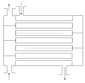
11. Recognize the given Shell and Tube Heat Exchanger.
a) 1-2 Shell and Tube
b) 2-3 Shell and Tube
c) 2-4 Shell and Tube
d) 3-6 Shell and Tube
View Answer
Explanation: In the provided figure, we see six passes for the tube (looking at the junctions and stops) and 2 partitioning walls present in the shell which divides it into three parts, hence the shown fig is a 3-6 Shell and Tube HE.
12. Which one of the following figures correctly represents counter-flow operation of a shell and tube heat exchanger with the specific heat of fluid in the shell side more than the fluid in the tube side?
a) 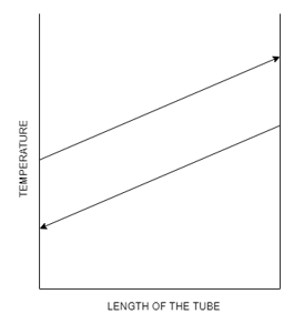
b) 
c) 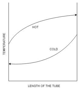
d) 
View Answer
Explanation: When we have MC×CC<MH×CH then the temperature profile shows a concave downward curve with the temperature of the hot fluid first slowly decreasing then rapidly falling as perfectly represented in the figure.
Sanfoundry Global Education & Learning Series – Heat Transfer Operations.
To practice all areas of Heat Transfer Operations, here is complete set of 1000+ Multiple Choice Questions and Answers.
If you find a mistake in question / option / answer, kindly take a screenshot and email to [email protected]
- Check Chemical Engineering Books
- Apply for Chemical Engineering Internship
- Check Heat Transfer Operations Books
- Practice Chemical Engineering MCQs
