This set of Heat Transfer Operations Multiple Choice Questions & Answers (MCQs) focuses on “Condensers – Refrigeration Systems”.
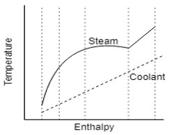
1. We divide the temperature/enthalpy diagram into a number of zones such that the curves of both the condensing stream and the coolant can be regarded as being reasonably linear.
a) True
b) False
View Answer
Explanation: In the thermal design of condenser it is impossible to assign a single demanding temperature difference and an overall heat transfer coefficient to the exchanger based on it, and hence we need a zonal or stepwise calculation of the surface area which is far more complicated than a HE because here we are taking linear groups of enthalpy curves for LMTD calculations.
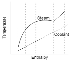
2. Which one of the following zone breaks can be correct regarded as valid for calculations?
a)
b) 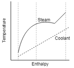
c) 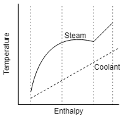
d) 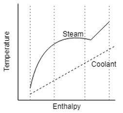
View Answer
Explanation: In a mixed vapour setup, we need to use a zonal or stepwise calculation of the surface area which is far more complicated than a HE because here we are taking linear groups of enthalpy curves for LMTD calculations.
Hence the correct option is the one with all the zones having nearly linear curves.
3. What do we apply at these linear zones of the diagram?
a) LMTD
b) Average Temperature difference
c) TSAT – TLIQUID
d) TSAT
View Answer
Explanation: In the thermal design of condenser it is impossible to assign a single demanding temperature difference and an overall heat transfer coefficient to the exchanger based on it, and hence we need a zonal or stepwise calculation of the surface area which is the LMTD for each zone.
4. Which one of the following parameters is not used while calculating zonal heat transfer coefficients for the zones in the diagram?
a) The resistance to heat transfer due to the tube wall
b) The resistance due to the film
c) The resistance to heat transfer associated with the presence of non-condensing gases
d) The coolant heat transfer coefficient
View Answer
Explanation: For calculating surface area requires evaluation of the local heat transfer coefficient at the zone boundaries which requires the calculation of –
- The coolant heat transfer coefficient, h
- The resistance to heat transfer due to the tube wall, 1/h
- The condensate heat transfer coefficient associated with heat transfer through a film of condensate on the tube wall, hC
- The resistance to heat transfer associated with the presence of non-condensing gases or a mixture
5. Fog formation in a condenser can occur when the temperature of the vapour-gas mixture _____________ the local saturation temperature during the condensation process.
a) Falls below
b) Goes above
c) Becomes equal to
d) Goes considerably high
View Answer
Explanation: Fog formation can occur when the temperature of the vapour-gas mixture falls largely below the saturation temperature during the condensation process at that temperature and pressure. This happens when the properties of a vapour-gas mixture and the process conditions have far more heat than mass removed from the mixture.
6. Condensers and evaporators together form a ____________
a) Heat Exchanger
b) Refrigeration system
c) Thermocouple
d) Heating System
View Answer
Explanation: The modern refrigeration systems use these two sets of equipments –
- To evaporate a refrigerant liquid in evaporator to pull in heat
- Condense the refrigerant in a condenser to release that heat
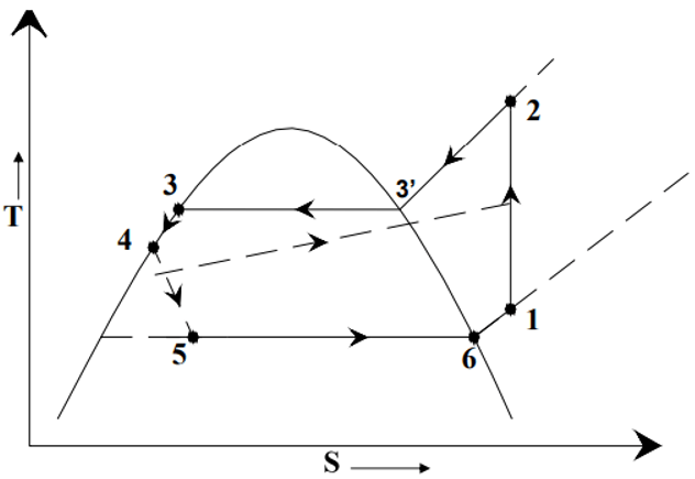
7. What does the following diagram represent?
a) Gas Cycle
b) Refrigeration cycle
c) Automobile engine cycle
d) 4stroke cycle
View Answer
Explanation: The modern refrigeration systems use these two sets of equipments –
- To evaporate a refrigerant liquid in evaporator to pull in heat
- Condense the refrigerant in a condenser to release that heat
Hence here the steps 2-4 is Condenser and rest is Evaporator.
8. Which process in the refrigeration diagram is represented as the heat rejection process?
a) 3-4-5-6
b) 2-3’-3-4
c) 3’-3-4-5
d) 3’-3-4
View Answer
Explanation: The process 2-3’-3-4 is the cumulative heat rejection process with
2-3’ = Superheated steam cooling
3’-3 = Condensation
3-4 = Cooling of condensate.
9. What set of process on the refrigeration cycle corresponds to that of the condenser?
a) 3-4-5-6
b) 2-3’-3
c) 3’-3-4-5
d) 2-3’-3-4
View Answer
Explanation: The process 2-3’-3-4 is the cumulative heat rejection process of a condenser with
2-3’ = Superheated steam cooling
3’-3 = Condensation
3-4 = Cooling of condensate.
10. What set of process on the refrigeration cycle corresponds to that of the evaporator?
a) 5-6-1-2
b) 2-3’-3
c) 3’-3-4-5
d) 2-3’-3-4
View Answer
Explanation: The process 5-6-1-2 is the cumulative heat absorption process of an evaporator with
5-6 = Evaporation
6-1 = Entropy increase
1-2 = Superheating of the evaporate.
11. The process 2-3’ is known as the ______________
a) Evaporation
b) De-superheating process
c) Condensation
d) Superheating process
View Answer
Explanation: The process 2-3’-3-4 is the cumulative heat rejection process of a condenser with
2-3’ = Superheated steam cooling
3’-3 = Condensation
3-4 = Cooling of condensate.
12. Which one of the following pathway represents the condensation process of the refrigerant in a refrigeration cycle?
a) 2-3’
b) 3-4
c) 3′-3
d) 1-2
View Answer
Explanation: The process 2-3’-3-4 is the cumulative heat rejection process of a condenser with
2-3’ = Superheated steam cooling
3’-3 = Condensation
3-4 = Cooling of condensate.
13. What is the name of the process occurring represented by the line 3-4 in the given refrigeration cycle?
a) Sensible, heating process
b) Sensible, sub cooling process
c) Entropy increase step
d) Condensation
View Answer
Explanation: The process 2-3’-3-4 is the cumulative heat rejection process of a condenser with
2-3’ = Superheated steam cooling
3’-3 = Condensation
3-4 = Cooling of condensate,sensible sub cooling process.
Sanfoundry Global Education & Learning Series – Heat Transfer Operations.
To practice all areas of Heat Transfer Operations, here is complete set of 1000+ Multiple Choice Questions and Answers.
If you find a mistake in question / option / answer, kindly take a screenshot and email to [email protected]
- Practice Chemical Engineering MCQs
- Apply for Chemical Engineering Internship
- Check Heat Transfer Operations Books
- Check Chemical Engineering Books
