This set of Heat Transfer Operations Questions & Answers for Exams focuses on “Extended Surface Heat Exchangers – Fins Industrial Use, Efficiency & its Overall Heat Transfer Coefficients”.
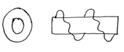
1. Recognize the following fin.
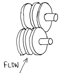
a) Individually finned tubes
b) Fully cut on Helix Fins
c) Flat (continuous) fins
d) Helix Fins
View Answer
Explanation: In the diagram shown above, the tubes are individually finned in the form of discs on every tubes separately. Hence the given fin is Individually finned tubes.
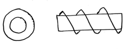
2. Recognize the following fin.
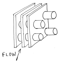
a) Individually finned tubes
b) Fully cut on Helix Fins
c) Flat (continuous) fins
d) Baffles
View Answer
Explanation: In the diagram shown above, the tubes are finned in the form of plates attached to each and every tube. Hence the given fin is Flat (continuous) fins.
3. Recognize the following fin.
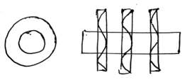
a) Slotted Wavy Helical
b) Wavy Disc
c) Fully cut on Helix Fins
d) Flat (continuous) fins
View Answer
Explanation: As in the diagram, we observe series of discs with wavy nature on each, shown by the wave inside the discs. Hence the given fin is Wavy Disc.
4. Recognize the following fin.
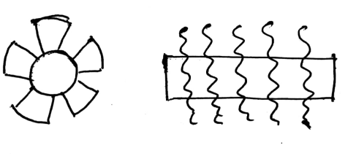
a) Individually finned tubes
b) Fully cut on axis of Helix Fins
c) Flat (continuous) fins
d) Baffles
View Answer
Explanation: In the left part of the diagram we observe cut on the fins which runs along the axis of the tube. Hence, this type of fin is usually used to increase the turbulence to a greater extent.
5. Recognize the following fin.
a) Individually finned tubes
b) Fully cut on axis of Helix Fins
c) Flat (continuous) fins
d) Helical Fins
View Answer
Explanation: The diagram on the left shows no cut and the right-side diagram shows a helical pattern, hence the given fin is a Helical one.
6. Recognize the following fin.
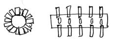
a) Studded Fins
b) Fully cut on axis of Helix Fins
c) Flat (continuous) fins
d) Helical Fins
View Answer
Explanation: The diagram show broken bits of plates attached to the surface of the tube usually by welding it onto it, also the diagram does not show any helical patterns. Hence these types of fins are called studded fins.
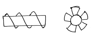
7. Recognize the following fin.
a) Double Helical
b) Fully cut on axis of Helix Fins
c) Flat (continuous) fins
d) Helical Fins
View Answer
Explanation: The figure represents a double helical fin as is clear from the fact that we observe two helixes running parallel to each other. These types of fins are one of the most commonly used in industry.
8. Recognize the following fin.
a) Double helical Fins
b) Studded Fins
c) Helical Fins
d) Annular Fins
View Answer
Explanation: The fins in the given diagram are annular type or disc fins attached to the tubes parallel to each other. Usually the outside fluid runs perpendicular to the tubes and parallel to the fins which facilitate high heat transfer rate.
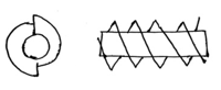
9. Recognize the following fin.
a) Wavy Helical
b) Helical
c) Studded Helical
d) Double Helical
View Answer
Explanation: As in the diagram, we observe Helixes with wavy nature on each, shown by the wave inside the helix, hence these fins are called wavy helical.
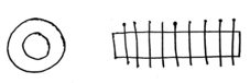
10. Recognize the following fin.
a) Cut on Helix
b) Partially cut on helix
c) Double helix
d) Serrated
View Answer
Explanation: The given helix is called serrated fins as the surface of the fin/ the extreme edges are serrated and hence it looks somewhat similar to fully cut on helix.
11. The utility of fin in dissipating a given quantity of heat is generally assessed on the basis of which of the parameters given?
a) Effectiveness and efficiency
b) Effectiveness
c) Efficiency
d) Fin length
View Answer
Explanation: The utility of fin in dissipating a given quantity of heat is generally assessed on the basis of the fin’s efficiency in increasing the heat transfer coefficient and its effectiveness.
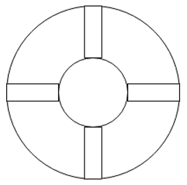
12. What is the heat transfer area for the following setup?
Given the thickness of fin = 5mm, diameter of inner and outer tube are 20mm and 40mm respectively and the length of tube is 1metre.
a) 0.3m2
b) 0.23m2
c) 0.123m2
d) 0.223m2
View Answer
Explanation: Total heat transfer area is the total wet surface area except the top surface
Hence the value is =(πDi-4xt+4x2xLfin)xL=\(\frac{(3.14X20-4X5+4X2X10)x1}{1000}\)=0.123m2.
13. What is the flow area of the given setup of fins in double pipe heat exchanger?
Given the thickness of fin = 5mm, diameter of inner and outer tube are 20mm and 40mm respectively and the length of tube is 1metre.
a) 742mm2
b) 642m2
c) 642mm2
d) 742m2
View Answer
Explanation: Total Flow area is the total cross-sectional.
Hence the value is = (\(\frac{π}{4}\)(Do2-Di2))- 4xtxLfin=\(\frac{3.14}{4}\)x(402-202)-4x5x10=742mm2.
14. What is the efficiency of an infinitely long fin?
a) \(\frac{1}{mL}\)
b) \(\frac{2}{mL}\)
c) \(\frac{3}{mL}\)
d) \(\frac{4}{mL}\)
View Answer
Explanation: For an infinitely long fin we have Efficiency E = \( \frac{\sqrt{hPKA}(T_b-T_∞)}{hA(T_b-T_∞)} = \frac{1}{mL}\) where mL = hP/kA.
15. What is the effectiveness of an infinitely long fin?
a) \(\frac{1}{mL}\)
b) \(\sqrt{\frac{KP}{hA_c}}\)
c) \(\sqrt{\frac{hP}{KA_c}}\)
d) \(\sqrt{hPKA}\)
View Answer
Explanation: The effectiveness of such a long fin is determined to be-
E = Qfin / Qno fin
Ab is the cross sectional area of the fin at the base
Qno fin represents the rate of heat transfer from this area if no fins are attached to the surface
∈FIN=\(\frac{Q_{FIN}}{Q_{NO\, FIN}}\frac{\sqrt{hPKA_c}(T_b-T_∞)}{hA_b(T_b-T_∞)}=\sqrt{\frac{KP}{hA_c}}\).
Sanfoundry Global Education & Learning Series – Heat Transfer Operations.
To practice all exam questions on Heat Transfer Operations, here is complete set of 1000+ Multiple Choice Questions and Answers.
If you find a mistake in question / option / answer, kindly take a screenshot and email to [email protected]
- Check Chemical Engineering Books
- Check Heat Transfer Operations Books
- Practice Chemical Engineering MCQs
- Apply for Chemical Engineering Internship
