This set of Environmental Engineering Multiple Choice Questions & Answers (MCQs) focuses on “Chemical Clarification”.
1. Which of the following represents the coagulant pipe in the following figure?
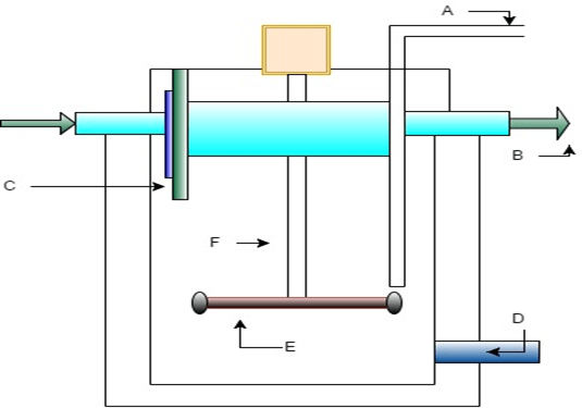
Figure: Flash mixer
a) A
b) B
c) C
d) D
View Answer
Explanation: ‘A’ represents the coagulant pipe which is used for discharging the coagulant into the flash mixer.
2. Which of the following represents the device which is used for sludge removal in the following figure?
Figure: Flash mixer
a) F
b) E
c) D
d) B
View Answer
Explanation: ‘D’ represents the drain valve which is used for the removal of sludge from the mixer.
3. _________ is the average of velocities at a point over a definite period of time.
Figure: Flash mixer
a) Mean velocity
b) Relative velocity
c) Velocity gradient
d) Temporal mean velocity
View Answer
Explanation: Temporal mean velocity is the average of velocities at a point over a definite period of time. It is represented by G.
4. Which of the following goes to the flocculation tank in the following figure?
Figure: Flash mixer
a) B
b) C
c) E
d) F
View Answer
Explanation: ‘B’ represents the outlet of the mixer which goes to the flocculation tank.
5. Which of the following is the correct expression regarding temporal mean velocity in the following figure?
Figure: Flash mixer
a) G = (P/μV)1/2
b) G = (P/μV)
c) G = (P/μV)2
d) G = (Pμ/V)1/2
View Answer
Explanation: Temporal mean velocity G = (P/μV)1/2, where P is the power, μ is the dynamic viscosity and V is the volume of the tank. It is measured in per second.
6. Which of the following is correctly paired in the following figure?
Figure: Flash mixer
a) C – Impeller
b) D – Outlet
c) F – Deflecting wall
d) E – Impeller
View Answer
Explanation: E represents the Impeller which is driven by the electric motor to revolve in the tank.
7. The speed of impeller in a flash mixer is ___________
Figure: Flash mixer
a) 45rpm
b) 60rpm
c) 110rpm
d) 200rpm
View Answer
Explanation: The speed of impeller in a flash mixer is between 100 to 120 rpm and the propeller type impeller is used.
8. ‘C’ in the following figure represents the ________
Figure: Flash mixer
a) Impeller
b) Impeller shaft
c) Deflecting wall
d) Flash mixer wall
View Answer
Explanation: ‘C’ represents the deflecting wall, whereas the boundary below the inlet and outlet of the tank is the flash mixer wall.
9. The detention period of a flash mixer is _________________
Figure: Flash mixer
a) 2 minutes
b) 30 minutes
c) 1 hour
d) 2 hours
View Answer
Explanation: The detention period of flash mixer lies between 30 seconds to 2 minutes.
10. Which of the following represents the impeller shaft in the following figure?
Figure: Flash mixer
a) F
b) E
c) C
d) B
View Answer
Explanation: Impeller is connected to impeller shaft which is further connected to electric motor so as to drive the impeller and mixing of coagulant in water takes place.
Sanfoundry Global Education & Learning Series – Environmental Engineering.
To practice all areas of Environmental Engineering, here is complete set of 1000+ Multiple Choice Questions and Answers.
If you find a mistake in question / option / answer, kindly take a screenshot and email to [email protected]
- Practice Mining Engineering MCQs
- Check Mining Engineering Books
- Apply for 1st Year Engineering Internship
- Check Environmental Engineering Books
