This set of Electronic Devices and Circuits Multiple Choice Questions & Answers (MCQs) focuses on “Modelling the Diode Forward Characteristic”.
1. Which of the following is method to model a diode’s forward characteristics?
a) Iteration method
b) Graphical method
c) Constant-voltage drop model
d) All of the mentioned
View Answer
Explanation: All of the mentioned are different methods used to model a diode’s forward characteristics.
2. A voltage regulator needs to provide a constant voltage in spite of the fact that there may be
a) Change in the load current drawn from the terminals of the regulator
b) Change of the DC power supply that feeds the regulator circuit
c) None of the mentioned
d) All of the mentioned
View Answer
Explanation: Voltage regulators are required in both of the situations mentioned.
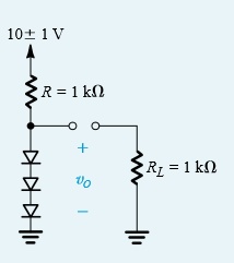
3. Calculate the %age change in the regulated voltage caused by a change of ±10% in the input voltage. (RL is not connected to the circuit)
a) ± 0.5%
b) ± 1%
c) ± 5%
d) ± 10%
View Answer
Explanation: Current I in the circuit = (10 – 2.1) / 1 or 7.9 mA
Incremental resistance of each diode is rd = 25mV/7.9mA at room temperature or 3.2Ω
Total resistance of the diode connection = r = 9.6Ω
The series combination of R and r acts as a voltage divider, hence
▲V0 = ±r/r+R or 9.5 mA or ± 0.5%.
4. Calculate the change in the voltage when RL is connected as shown below.
a) -10 mA
b) -15 mA
c) -20 mA
d) -25 mA
View Answer
Explanation: When RL is connected it draws approx. 2.1v/1000 A current or 2.1 mA. Hence the current in the diode decreases by approximately 2.1 mA. The voltage change across the diode is thus -2.1mA * 9.6 Ω or -20mA.
5. The value of the diode small-signal resistance rd at bias currents of 0.1 mA is
a) 250 Ω
b) 25 Ω
c) 2.5 Ω
d) 0.25 Ω
View Answer
Explanation: Thermal voltage at room temperature is 25mV and the current is 0.1mA. rd = 25mV/0.1mA or 250 Ω.
6. In many applications, a conducting diode is modeled as having a constant voltage drop, usually approximately
a) 1 V
b) 0.1 V
c) 0.7 V
d) 7V
View Answer
Explanation: Normally a silicon diode has a voltage drop of 0.7V.
7. The graphical method of modeling a diode characteristics is based on
a) Iteration method
b) Constant voltage drop method
c) Small signal approximation
d) Exponential method
View Answer
Explanation: Graphical method uses equations obtained in the exponential method and then the Answer of these equations is obtained by plotting them on a graph.
8. For small-signal operation around the dc bias point, the diode is modeled by a resistance equal to the
a) Slope of the i-v characteristics of the diode at the bias point
b) Square root of the slope of the i-v characteristics of the diode at the bias point
c) Inverse of the slope of the i-v characteristics of the diode at the bias point
d) Square root of the inverse of the slope of the i-v characteristics of the diode at the bias point
View Answer
Explanation: It is a required characteristic for small-ground operations.
9. The other name for bias point is
a) Quiescent point
b) Node point
c) Terminal point
d) Static point
View Answer
Explanation: Quiescent point is also called base point. It is due to this name that is also called Q–point.
10. In iteration method for modelling a diode the answer obtained by each subsequent iteration is
a) Is close to the true value
b) Is close to the value obtained by exponential method
c) All of the mentioned
d) None of the mentioned
View Answer
Explanation: True value is obtained by the exponential method and therefore both of the statements are true.
Sanfoundry Global Education & Learning Series – Electronic Devices and Circuits.
To practice all areas of Electronic Devices and Circuits, here is complete set of 1000+ Multiple Choice Questions and Answers.
If you find a mistake in question / option / answer, kindly take a screenshot and email to [email protected]
