This set of Electronic Devices and Circuits Multiple Choice Questions & Answers (MCQs) focuses on “Basic BJT Amplifier Configuration”.
1. An amplifier is measured to have an internal resistance of 10 kΩ, voltage gain of 100V/V and output resistance of 100 Ω. Also, when a load resistance of 1 kΩ is connected between the output resistance if found to decrease to 8 kΩ. If the amplifier is fed with the signal source having an internal resistance of 2 kΩ. Find Gm.
a) 1 A/V
b) 10 A/V
c) 100 A/V
d) 1000 A/V
View Answer
Explanation: Gm = (voltage gain in V/V) / (output resistance) or 100/100 A/V.
2. An amplifier is measured to have an internal resistance of 10 kΩ, voltage gain of 100V/V and output resistance of 100 Ω. Also, when a load resistance of 1 kΩ is connected between the output resistance if found to decrease to 8 kΩ. If the amplifier is fed with the signal source having an internal resistance of 2 kΩ. Find Av.
a) 9.09 V/V
b) 10 V/V
c) 90.9 V/V
d) 100 V/V
View Answer
Explanation: Av = Avo X Rl/Ro+Rl or 100 X 1000/1000+100 or 90.9 V/V.
3. An amplifier is measured to have an internal resistance of 10 kΩ, voltage gain of 100V/V and output resistance of 100 Ω. Also, when a load resistance of 1 kΩ is connected between the output resistance if found to decrease to 8 kΩ. If the amplifier is fed with the signal source having an internal resistance of 2 kΩ. Find Gvo.
a) 53.3 V/V
b) 63.3 V/V
c) 73.3 V/V
d) 83.3 V/V
View Answer
Explanation: Gvo = (Avo X input resistance) / (input resistance + signal resistance).
4. An amplifier is measured to have an internal resistance of 10 kΩ, voltage gain of 100V/V and output resistance of 100 Ω. Also, when a load resistance of 1 kΩ is connected between the output resistance if found to decrease to 8 kΩ. If the amplifier is fed with the signal source having an internal resistance of 2 kΩ. Find Gv.
a) 53.4 V/V
b) 72.7 V/V
c) 83.3 V/V
d) 90.9 V/V
View Answer
Explanation: Gv = (Gvo X Av) / Avo or 83.3 X 90.9 / 100 V/V.
5. An amplifier is measured to have an internal resistance of 10 kΩ, voltage gain of 100V/V and output resistance of 100 Ω. Also, when a load resistance of 1 kΩ is connected between the output resistance if found to decrease to 8 kΩ. If the amplifier is fed with the signal source having an internal resistance of 2 kΩ. Find R out.
a) 146 Ω
b) 292 Ω
c) 584 Ω
d) 1168 Ω
View Answer
Explanation: Rout = Rl (1 – Gvo/Gv). Put in the respective values and solve.
6. An amplifier is measured to have an internal resistance of 10 kΩ, voltage gain of 100V/V and output resistance of 100 Ω. Also, when a load resistance of 1 kΩ is connected between the output resistance if found to decrease to 8 kΩ. If the amplifier is fed with the signal source having an internal resistance of 2 kΩ. Find Ai.
a) 182 A/A
b) 364 A/A
c) 546 A/A
d) 728 A/A
View Answer
Explanation: (Vo X R in) / (Vi X Rl) gives the required value of Ai.
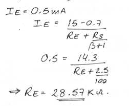
7. The circuit shown below is a small sine wave signal with average zero and transistor ß. Find the value of R(E) to establish a dc emitter current of about 0.5 mA.
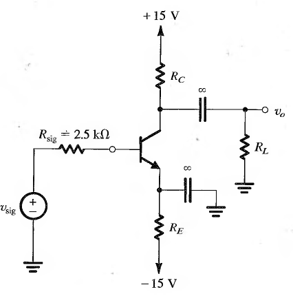
a) 28.57 kΩ
b) 57.04 kΩ
c) 114.08 kΩ
d) 228.16 kΩ
View Answer
Explanation:
8. The circuit shown below is a small sine wave signal with average zero and transistor ß. Find R(C) to establish a dc collector voltage of about +5V.
a) 5 kΩ
b) 10 kΩ
c) 15 kΩ
d) 20 kΩ
View Answer
Explanation: Vc = 15 – Rc.Ic
5 = 15 – Rc * 0.99 * 0.5m
Rc = 20.2kΩ
= 20kΩ.
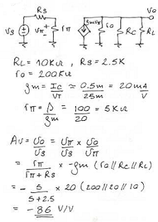
9. The circuit shown below is a small sine wave signal with average zero. For R (L) = 10 kΩ and transistor Ro = 200 kΩ, determine the overall voltage gain.
a) -21 V/V
b) -42 V/V
c) -86 V/V
d) -123 V/V
View Answer
Explanation:
Sanfoundry Global Education & Learning Series – Electronic Devices and Circuits.
To practice all areas of Electronic Devices and Circuits, here is complete set of 1000+ Multiple Choice Questions and Answers.
If you find a mistake in question / option / answer, kindly take a screenshot and email to [email protected]
