This set of Electrical Machines Multiple Choice Questions & Answers (MCQs) focuses on “Synchronous Motor Phasor Diagram”.
1. Below is the phasor diagram of synchronous generator.
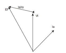
If the machine is made to run as synchronous motor, what will be the phasor diagram changes then?
a) Reverse Ia
b) Reverse Ef
c) Reverse Vt and Ia
d) Reverse Vt
View Answer
Explanation: Only the direction of the armature current changes in the motor as it absorbs the electrical energy.
2. Below is the phasor diagram of synchronous generator.
If the machine is made to run as synchronous motor, what will be the new phasor diagram?
a)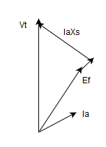
b)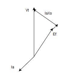
c)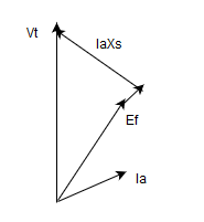
d)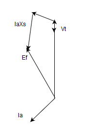
View Answer
Explanation: Only the direction of the armature current changes in the motor as it absorbs the electrical energy. It has a component in phase opposite to Ef.
3. The voltage equation of synchronous motor is?
a) Ef = Vt + Ia*(ra+jXa)
b) Ef = Vt – Ia*(ra+jXa)
c) Ef = Vt + Ia*(ra-jXa)
d) Ef = Vt – Ia*(ra-jXa)
View Answer
Explanation: The voltage equation of synchronous motor is Ef = Vt + Ia*(ra+jXa).
4. Synchronous motor delivers lagging power at __________
a) leading pf
b) lagging pf
c) zero pf
d) unity pf
View Answer
Explanation: As Q < 0 for synchronous motor at leading pf.
5. A 420 V synchronous motor is working at 30° lagging load. What can be the expected phasor?
a)
b)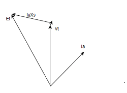
c)
d) None of the mentioned
View Answer
Explanation: The Ia should lag Ef by 30°.
6. The synchronous motor is operating at upf load. The most suitable phasor will be?
a) 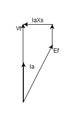
b)
c)
d)
View Answer
Explanation: Ia must be in phase with the Ef.
7. The zero power factor of an alternator can be obtained by _________ at rated Ia.
a) over exciting
b) conducting short circuit of secondary terminals
c) under excitation
d) running as reluctance motor
View Answer
Explanation: By over exciting an alternator gives the additional flux required to make it operate at zero power factor.
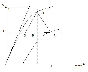
8. From the figure shown below for the OCC and SCC of a three phase alternator, the point ‘L’ corresponds to _______ and the point ‘A’ can be obtained by _____ the alternator.
a) terminal voltage, over exciting
b) excitation voltage, over exciting
c) terminal voltage, under exciting
d) excitation voltage, under exciting
View Answer
Explanation: The point ‘L’ corresponds to Vt and the point ‘A’ can be obtained by over exciting the alternator.
9. In the figure below, the point ‘F’ corresponds to _______ which can be obtained by ________
a) field current required to circulate short circuit current, SCC
b) field current required to circulate full load current, SCC
c) mmf required to cancel the hysteresis losses, SCC
d) mmf required to compensate the leakage reactances, SCC
View Answer
Explanation: Point ‘F’ corresponds to the short circuit current and it is obtained by SCC plot.
10. The operating point for an over excited alternator working near zpf lagging power factor gives ‘A’ as the operating point. Then if the same machine is working as an over excited synchronous motor will give same operating point at __________
a) zpf leading
b) zpf lagging
c) upf
d) there will never be the same operating point for the machine as motor as well as generator
View Answer
Explanation: Yes, by making it from lag to leading power factor, a synchronous machine can have same operating point for the alternator as well as synchronous motor.
11. Identify the over excited alternator operating at zpf.
a) 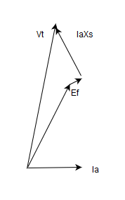
b) 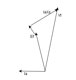
c) 
d) 
View Answer
Explanation: Ef>Vt, makes it work as over excited.
12. Identify the over excited synchronous motor operating at zpf.
a)
b) 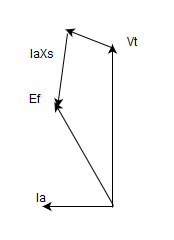
c)
d)None of the mentioned
View Answer
Explanation: Ef>Vt, and the Ia is in opposite to that of alternator.
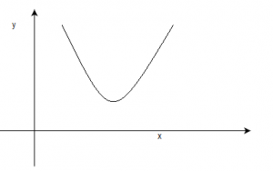
13. For the below graph depicting the performance of a synchronous motor, coordinates ‘x’ and ‘y’ are respectively?
In the ‘V’ curve shown in the above figure for a synchronous motor, the parameter of x and y coordinates are, respectively.
a) Armature current and field current
b) Power factor and field current
c) Armature current and torque
d) Torque and field current
View Answer
Explanation: V curve is between the armature current and the field current.
14. We can increase the torque of a reluctance synchronous motor if we __________
a) Increase reluctance of the magnetic circuit along the direct axis
b) Decrease the reluctance of the magnetic circuit along the quadrature axis
c) Increase the ratio of the quadrature axis reluctance to direct axis reluctance
d) Decrease the ratio of quadrature axis reluctance to direct axis reluctance
View Answer
Explanation: Te = -1/2(φ^2)(Rlq-Rld) sin2δ.
15. Switched reluctance motors are basically __________
a) salient pole synchronous motor but without excitation winding
b) stepper motor with salient poles
c) synchronous motor with salient poles on stator and rotor
d) stepper motor with closed loop control and with rotor position sensor
View Answer
Explanation: A switched reluctance motor has stepper motor.
Sanfoundry Global Education & Learning Series – Electrical Machines.
To practice all areas of Electrical Machines, here is complete set of 1000+ Multiple Choice Questions and Answers.
If you find a mistake in question / option / answer, kindly take a screenshot and email to [email protected]
- Check Electrical Machines Books
- Apply for Electrical & Electronics Engineering Internship
- Practice Electrical & Electronics Engineering MCQs
- Check Electrical Engineering Books
- Apply for Electrical Engineering Internship
