This set of Electrical Machines Multiple Choice Questions & Answers (MCQs) focuses on “Induction Motor Phasor Diagram”.
1. The rotor of the slip ring induction motor is connected to an ac source and stator is short circuited. If the rotating magnetic field is rotates clockwise, the rotor rotates in _________
a) anticlockwise
b) clockwise
c) remains stationary
d) any of the mentioned
View Answer
Explanation: Rotor will rotate in anticlockwise direction as the net speed w.r.t. stator should be stationary.
2. Rotor leakage impedance at starting is different from its value at normal running conditions.
a) True
b) False
View Answer
Explanation: The rotor leakage impedance depends on the slip of the machine. Slip varies with the running conditions.
3. If the hysteresis is neglected in the induction machine, then the the air gap flux _______ the resultant mmf.
a) is in phase with
b) lags
c) leads by a small angle
d) can not decide the nature of the operation
View Answer
Explanation: When the hysteresis loss is neglected, then the air gap flux will be in phase with the resultant mmf.
4. On increasing the starting torque of the induction motor, the maximum torque is also increased.
a) False
b) True
View Answer
Explanation: It is false, as the starting torque and the maximum torque are independent of each other.
5. Approximately the efficiency of the rotor of the induction motor depends on the _________
a) rotor speed
b) synchronous speed
c) rotor speed and synchronous speed
d) magnetic field speed
View Answer
Explanation: Efficiency of the rotor is approximately equal to ratio of speed of rotor to synchronous speed.
6. A 400, 3-phase, 50 Hz, 4 pole induction motor takes a line current of 10 A with 0.86 pf lagging. What is the stator input?
a) 5.95 kW
b) 6.95 kW
c) 4.45 kW
d) 8.38 kW
View Answer
Explanation: P = 1.73*V*I*cosθ = 1.73*400*10*0.86 = 5.958 kW.
7. The power input to the 3-phase induction motor is 60 kW. The stator losses total 1 kW. Find the mechanical power developed at the slip of 3%.
a) 57.23 kW
b) 58 kW
c) 56.8 kW
d) 59 kW
View Answer
Explanation: Air gap power = 60-1 = 59 kW
Pm = (1-s)Pag = 0.97*59 = 57.23 kW.
8. Choose the most appropriate. The torque slip characteristic of the induction motor at the slip of 3-6 %.
a) 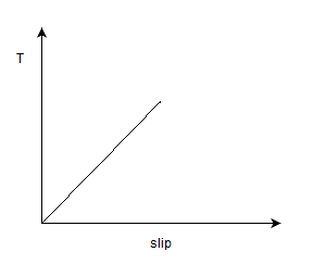
b) 
c) 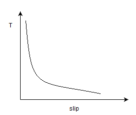
d) 
View Answer
Explanation: At low slip regions, T α s*V^2/R2.
9. The torque and the slip characteristic is most correctly related by which of the following below in the region of 30-50% operation of slip.
a)
b)
c)
d)
View Answer
Explanation: At the higher values of the slip, T α 1/s.
10. An induction motor X operating at the slip of 3%. An induction motor Y operating at slip of 40%.
a) Machine X is only stable
b) Machine Y is only stable
c) Both the machine X and Y are stable
d) Neither X nor Y is stable
View Answer
Explanation: Induction motor operates stable in the low slip regions as the losses are reduced.
11. A 3-phase induction motor had the maximum rated torque of 40 N-m while the load torque applied to it is 55 N-m.
a) The machine will become unstable
b) The machine will operate in stable region
c) The machine will get heated up
d) The machine will run at dangerously high speed
View Answer
Explanation: Induction motor is unstable when the load torque is more the the maximum torque of the machine.
12. I. Maximum torque can be achieved by inserting an additional resistance at desired slip in the rotor.
II. Maximum torque can be altered by adding the external resistance in the rotor.
a) Only I is true
b) Both I and II are true
c) Neither I nor II is true
d) Only II is true
View Answer
Explanation: Maximum torque is independent of the resistance.
13. If the frequency is reduced by 50% for a 3-phase, 50 Hz induction motor having 4 poles. The slip at which the maximum torque occurs becomes _________
a) 2*s
b) s
c) 1/2s
d) 1/s
View Answer
Explanation: s = r/x
s α 1/f.
If the frequency is reduced to half, slip increases to twice.
14. If the voltage of a three phase induction motor if increased to 200%, then the slip if the machine changes to _________
a) 1/s
b) s
c) 1/2s
d) 2*s
View Answer
Explanation: The slip will remain independent of the operating voltage.
15. If the voltage and frequency of the induction machine is reduced to 50% of the operating region,the slip of the machine will be?
a) 2*s
b) s
c) 1/2s
d) 1/s
View Answer
Explanation: Slip α 1/f; Even though the flux remains constant as the v/f ratio is constant.
16. If the operating voltage of the induction motor is increased by twice while keeping the frequency of the operation constant. Then the new starting torque will be?
a) 4*T
b) 1/4*T
c) T
d) 2*T
View Answer
Explanation: Tst α V^2.
T2/T1 = (2/1)^2
T2 = 4*T1.
17. The phasor diagram for the induction motor is?
a)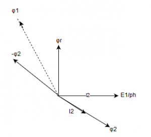
b)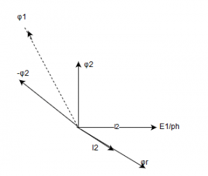
c)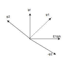
d)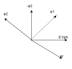
View Answer
Explanation: Relative space angle between the two rotating magnetic fields is 90+θ.
18. The phasor diagram for the induction generator is best represented by?
a)
b)
c)
d)
View Answer
Explanation: Relative space angle between the two rotating magnetic fields is 90-θ.
Sanfoundry Global Education & Learning Series – Electrical Machines.
To practice all areas of Electrical Machines, here is complete set of 1000+ Multiple Choice Questions and Answers.
If you find a mistake in question / option / answer, kindly take a screenshot and email to [email protected]
- Check Electrical Engineering Books
- Practice Electrical Engineering MCQs
- Check Electrical Machines Books
- Apply for Electrical & Electronics Engineering Internship
- Apply for Electrical Engineering Internship
