This set of Electrical Machines Multiple Choice Questions & Answers (MCQs) focuses on “Circle Diagrams of Induction Machines”.
1. Circle diagram of an induction motor is graphical representation of ____________
a) its equivalent circuit
b) its rotor equivalent
c) its stator equivalent
d) its stationary equivalent circuit
View Answer
Explanation: Circle diagram gives information about the equivalent circuit of the induction motor.
2. Circle diagram depicts the relation between ____________
a) stator current and the slip variation
b) rotor current and stator current
c) slip variation and the power factor
d) slip variation and the losses of the machine
View Answer
Explanation: Circle diagram shows extermeties of stator current and the slip variation.
3. A 10kW, 50 Hz, 3-phase induction motor develops the rated torque at 1440rpm. If the load torque is reduced to half, then the motor speed is?
a) 1470rpm
b) 1410rpm
c) 1400rpm
d) 1444rpm
View Answer
Explanation: Slip = 0.04
T2/T1 = s2/s1
s2 = (1/2)*0.04 = 0.02
Nr = (1-0.02)*1500 = 1470 rpm.
4. A 10kW, 50 Hz, 3-phase induction motor develops the rated torque at 1440rpm. If the load torque is reduced to half, then the power output that can now be obtained is?
a) 5 kW
b) 5.3 KW
c) 4.6 kW
d) 8 kW
View Answer
Explanation: s2 = (1/2)*0.04 = 0.02
P = (10000*60*2*3.14*1470)/(2*2*3.14*1460*60)
P = 5.03 kW.
5. In a 3-phase induction motor, the flux per pole will vary with the slip is?
a) 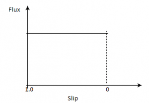
b) 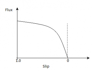
c) 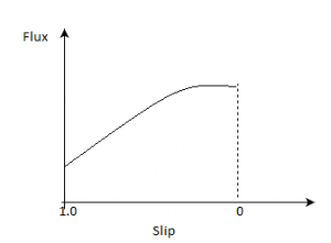
d) 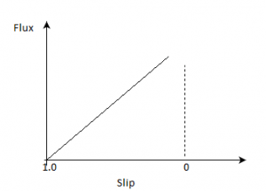
View Answer
Explanation: Flux remains constant throughout the operation of the induction motor.
6. The rotor mmf per pole in the 3-phase, 4-pole induction motor varied with slip is?
a) 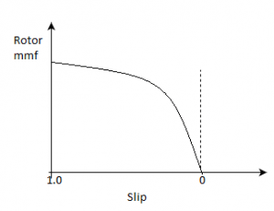
b) 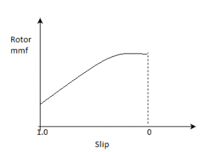
c) 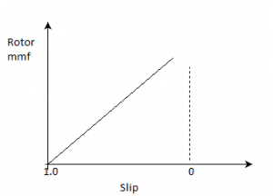
d) 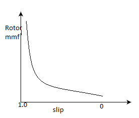
View Answer
Explanation: As slip decreases, the rotor current decreases so the rotor mmf.
7. Blocked rotor test is conducted to find the ____________
a) leakage impedance
b) leakage reactance
c) stator impedance
d) rotor impedance
View Answer
Explanation: Blocked rotor test determines the leakage impedance and so the core losses.
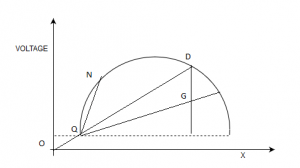
8. In the below circle diagram, OG represents?
a) Rated torque
b) Maximum torque
c) Rated power output
d) Losses
View Answer
Explanation: OG is the rated torque.
9. In the following circle diagram of the induction motor, QN is the ____________
a) rotor current referred to stator
b) stator current
c) stator current referred to rotor
d) no load input to rotor
View Answer
Explanation: It is rotor current referred to stator.
10. Stator resistance can be measured using Kelvin’s double bridge.
a) True
b) False
View Answer
Explanation: Stator has very low resistance, so it is most accurately observed by using a kelvin’s double bridge.
11. If the no load test is conducted at its rated frequency but less than the rated voltage, then the wattmeter reading will be ____________
a) reduced
b) more than previous reading
c) remain same
d) none of the mentioned
View Answer
Explanation: No load losses will reduce, so the power consumption.
12. If the no load test is conducted at its rated frequency but less than the rated voltage, then the mechanical losses will _____ and the constant losses will _________
a) constant, reduce
b) constant, rise
c) reduce, rise
d) constant, constant
View Answer
Explanation: Mechanical losses remain always constant, but the stator losses will reduce as the voltage has been decreased.
13. No load power factor of the induction motor will __________ if the no load test is conducted at its rated frequency but less than the rated voltage.
a) improve
b) degrade
c) remain same
d) none of the mentioned
View Answer
Explanation: It will improve.
14. If the no load test is conducted at its rated voltage but less than the rated frequency.
A. The wattmeter reading will be more than previous.
B. The power factor will also improve.
a) Only A is true
b) Only B is true
c) Both A as well as B are true
d) None of the mentioned
View Answer
Explanation: Flux increases as flux = V/f. So the magnetizing current also increases. Power factor decreases.
15. Circle diagram for the fixed rotor resistance and variable reactance is most appropriately shown by?
a) 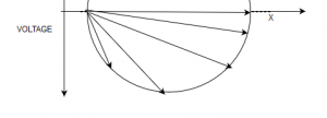
b) 
c) 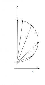
d) 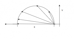
View Answer
Explanation: |I| = |V/Z|
θ = atan(x/r), Here reactance is variable, which maps a semicircle in its locus diagram.
16. Circle diagram for the variable rotor resistance and fixed reactance is most appropriately shown by
a) 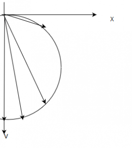
b)
c)
d)
View Answer
Explanation: |I| = |V/Z|
θ = atan(x/r), Resistance is varying, so the locus will be a semi circle.
17. Use the below circle diagram to choose the correct option.
a) CF: Rotor copper loss, FG: Stator copper loss, GE: Fixed losses.
b) FG:Rotor copper loss, CF: Stator copper loss, GE: Fixed losses.
c) GE:Rotor copper loss, FG: Stator copper loss, CF: Fixed losses.
d) FG:Rotor copper loss, CF: Stator copper loss, CF: Core losses.
View Answer
Explanation: GE is fixed losses. From the F to top the rated rotor copper losses occur.
18. In the following circle diagram, what is CC’?
a) full load condition
b) no load condition
c) fixed losses
d) rated full load losses
View Answer
Explanation: It is full load condition.
Sanfoundry Global Education & Learning Series – Electrical Machines.
To practice all areas of Electrical Machines, here is complete set of 1000+ Multiple Choice Questions and Answers.
If you find a mistake in question / option / answer, kindly take a screenshot and email to [email protected]
