This set of Electric Circuits Multiple Choice Questions & Answers (MCQs) focuses on “The Inverting and Non-Inverting Amplifier Circuit”.
1. The opamp in the Inverting circuit is in __________
a) Linear region
b) Saturation
c) Cut-off region
d) Non-linear region
View Answer
Explanation: We assume that the opamp is in linear region.
2. In an Inverting Amplifier circuit, the output voltage vo is expressed as a function of ____________
a) Input current
b) Output current
c) Source voltage
d) Source current
View Answer
Explanation: The goal of an inverting circuit is to express output voltage vo as a function of source voltage vs.
3. The other name for Gain is ____________
a) Scaling factor
b) Output
c) Amplifying factor
d) Scaling level
View Answer
Explanation: The gain is also known as scaling factor and it is the ratio of Rf/Rs in case of an Inverting amplifying circuit.
4. If VCC = 12V and vs=1mV, then Rf/Rs is _____________
a) >12000
b) <12000
c) 12000
d) 1
View Answer
Explanation: Rf/Rs ≤ │VCC/vs│.
5. In the expression vo= -Avn, A is called ______________
a) Closed loop gain
b) Closed loop fault
c) Open loop fault
d) Open loop gain
View Answer
Explanation: A is called open loop gain.
6. The circuits of an inverting and Non-Inverting amplifying comprises of __________ and _______ number of resistors.
a) 3, 2
b) 2, 3
c) 2, 2
d) 3, 3
View Answer
Explanation: Inverting amplifying circuit- Rs, Rf.
Non-Inverting amplifying circuit – Rs, Rf, Rg.
7. The condition for a Non-inverting amplifying circuit to operate in linear region operation _____________
a) (Rs+Rf)/Rs < │VCC/vg│
b) (Rs+Rf)/Rs ≠ │VCC/vg│
c) (Rs+Rf)/Rs > │VCC/vg│
d) (Rs+Rf)/Rs = │VCC/vg│
View Answer
Explanation: Assume that opamp is ideal. The condition for the linear region operation in a Non-inverting amplifying circuit is (Rs+Rf)/Rs <│VCC/vg│.
8. If Rs= 3Ω, Rf= 6Ω then the relation between vo and vg in case of a Non-Inverting amplifying circuit.
a) vo= 9vg
b) vo= 6vg
c) vo= 3vg
d) vo= vg
View Answer
Explanation: vo= ((Rs+Rf)/Rs) *vg.
9. If Rs= 5Ω, Rf= 25Ω and -2.5V ≤ vg ≤ 2.5V. What are the smallest power supply voltages that could be applied and still have opamp in linear region?
a) ±9V
b) ±2.5V
c) ±6V
d) ±15V
View Answer
Explanation: vo= ((Rs+Rf)/Rs) *vg. By substituting the values, we have vo=6vg.
vo=6(-2.5) = -15
vo=6(2.5) =15.
10. If an inverting amplifying circuit has a gain of 10 and ±15V power supplies are used. The values of input for which opamp would be in the linear region?
a) ±1.25
b) ±1.5V
c) ±2.25
d) ±0.5
View Answer
Explanation: Gain= Rf/Rs= 10 and vo= (-Rf/Rs)*vs.
→ vo= -10vs and given -12V≤ vo ≤ 12V.
→ -15= -10vs. So, vs= 1.5V
→ 15=-10vs. So, vs=-1.5V.
11. If the gain of an inverting amplifying circuit is 13 and ±22V power supplies are used. What range of input values allows the opamp to be in linear region?
a) ±1.69
b) ±1.35V
c) ±2.28
d) ±0.5
View Answer
Explanation: Gain= Rf/Rs= 13 and vo= (-Rf/Rs)*vs.
→ vo= -13vs and given -22V≤ vo ≤ 22V.
→ -22= -13vs. So, vs=1.692 V
→ 22=-13vs. So, vs=-1.692V.
12. The input applied to an Inverting amplifier is ______________
a) Equal to output
b) Equal to Inverted output
c) Not equal to output
d) Output is equal to input
View Answer
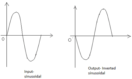
Explanation: The name itself indicates it is an Inverting amplifier. So, the input applied is inverted and is given as output. Suppose the input applied is sinusoidal then, the output is
13. In R1=10kΩ, Rf=100kΩ, v1=1V. A load of 25kΩ is connected to the output terminal. Calculate i1 and vo.
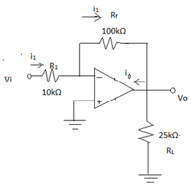
a) 0.5mA, 10V
b) 0.1mA, 10V
c) 0.1mA, -10V
d) 0.5mA, -10V
View Answer
Explanation: i1= v1/R1 = 1V/10kΩ = 0.1mA
V0= -(Rf/R1)*v1 = -(100kΩ/10kΩ)*1V = -10V.
Sanfoundry Global Education & Learning Series – Electric Circuits.
To practice all areas of Electric Circuits, here is complete set of 1000+ Multiple Choice Questions and Answers.
If you find a mistake in question / option / answer, kindly take a screenshot and email to [email protected]
- Apply for Electronics & Communication Engineering Internship
- Practice Electrical Engineering MCQs
- Practice Electronics & Communication Engineering MCQs
- Check Electrical Engineering Books
- Check Electric Circuits Books
