This set of Cognitive Radio Problems focuses on “Next Generation Wireless Network – Position Awareness – 2”.
1. Which among the following is not an outcome of destination location addressing?
a) Reduced interference
b) Reduced power consumption
c) Reduced handovers
d) Reduced dropped calls
View Answer
Explanation: Destination location addressing propagates via only known nodes in a path to reach the destination. This prevents signal propagation from running off course and optimizes power consumption. It also results in the reduction of interference and dropped calls by combining the knowledge of geolocation, velocity vector, and planned path.
2. Which among the following is not a common feature between the time of arrival and time difference of arrival?
a) Straight-line of sight
b) High resolution system clock
c) Propagation at speed of light
d) Shape of curve
View Answer
Explanation: Time of arrival and time difference of arrival are two time-based approaches. Both approaches require a high-resolution system clock with signals that propagate at the speed of light. It requires a straight line of sight path as the signal delay directly relates to the line of sight distance.
3. Which among the following is not a step in time of arrival and time difference of arrival process?
a) Analysis of signal propagation
b) Track error bound
c) Conversion to equation
d) Analysis of channel path
View Answer
Explanation: The signal propagation is analyzed by multiple receivers or by multiple antennas. This results in the conversion of the time delay to the phase difference, time difference, or frequency shift which is then converted to equations of range, or other parameters.
4. Which among the following is an essential for the time of arrival approach?
a) Time tag and phase tag the transmitted signal
b) Phase tag the transmitted signal
c) Time tag and frequency tag the transmitted signal
d) Time tag the transmitted signal
View Answer
Explanation: The time of arrival approach relies on time tagging the transmitted signal and computing the time of arrival of the signal at the receiver. When many receivers with known locations obtain the same signal, the multiple iso-range spheres intersect providing the location of the transmitter. Likewise, when transmitters provide knowledge of their location in the time-tagged transmitted signal, a receiver can compute its location.
5. What curve is obtained by plotting the time difference of arrival?
a) Parabola
b) Sphere
c) Hyperbola
d) Ellipse
View Answer
Explanation: The time difference of arrival approach involves computing the time difference between the reception of a signal at one location and the reception of the same signal at a different location. The plot of time difference of arrival produces a hyperboloid surface with its foci at the two receivers.
6. How many surfaces are required to geolocate a transmitter on a two-dimensional plane using time difference of arrival approach?
a) Two
b) Three
c) Four
d) Five
View Answer
Explanation: When a number of receivers at known locations receive the same sign, the obtained hyperboloids intersect at the location of the transmitter. The number of surfaces required to geolocate a transmitter in 2 D plane is three and the number of surfaces required to geolocate a transmitter in 3 D plane is four.
7. What type of signal is employed by LORAN?
a) Intermittent
b) Continous
c) Burst
d) Buffer
View Answer
Explanation: LORAN system sends a known burst signal with fixed periodicity from multiple transmitters. The receivers construct time difference of arrival hyperboloid curve to determine the location of the transmitter. LORAN provides published charts corresponding to hyperboloid curves, to find the intersection of two-time difference pairs.
8. Which among the following is the first step in the determination of position using time difference of arrival?
a) Time tag the transmitted signal
b) Solving for the position of source transmitter
c) Determining the time difference of arrival curve
d) Conversion to a common coordinate system
View Answer
Explanation: The hyperboloid curve of time difference of arrival approach is drawn by considering the speed of propagation and difference between the arrival times of the same signal at two receivers. To expand the curve to include three receivers, the results are converted to a common coordinate system. Finally, the curve equations are solved to identify the position of the source.
9. Which among the following computations might be employed as a technique for determining the time difference of arrival?
a) Cross-correlation
b) Probability density function
c) Cumulative density function
d) Standard deviation
View Answer
Explanation: Time can be estimated using correlation in a wideband transmission environment. In time difference of arrival approach, the received signals are digitized in their corresponding stations and are transferred to a common processing location for calculating cross correlation. The peak of the cross correlation provides the time difference of arrival.
10. The angle of arrival approach requires antenna array at the receivers.
a) True
b) False
View Answer
Explanation: In the angle of arrival approach, multiple receivers combine to compute the angle of arrival. The technique requires an antenna array at the receivers. The bearing to the signal and the known location of multiple receivers provide the location of the transmitter.
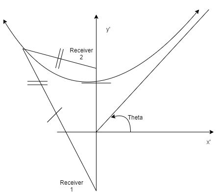
11. Which among the given conditions is represented in the following diagram?
a) Hyperbola one receiver and source in the same plane and the second receiver in another plane
b) Hyperbola with two receivers and source in the same plane
c) Hyperbola with two receivers in the same plane and source in another plane
d) Hyperbola with each receiver in one plane and a source in another plane
View Answer
Explanation: The time difference of arrival approach involves computing the time difference between the reception of a signal at one location and the reception of the same signal at a different location. The hyperboloid curve of time difference of arrival approach is drawn by considering the speed of propagation and difference between the arrival times of the same signal at two receivers. When the receivers and the source are present in the same plane, the hyperbola appears V-shaped with an axis of symmetry through the two receivers.
Sanfoundry Global Education & Learning Series – Cognitive Radio.
To practice all areas of Cognitive Radio Problems, here is complete set of 1000+ Multiple Choice Questions and Answers.
If you find a mistake in question / option / answer, kindly take a screenshot and email to [email protected]
