This set of Civil Engineering Drawing Multiple Choice Questions & Answers (MCQs) focuses on “Sections of Solids”.
1. ___________are multi-view technical drawings that contain special views of a part or parts, that reveal interior features.
a) 3d drawing
b) Isometric drawing
c) Hatched drawing
d) Sectional drawings
View Answer
Explanation: Sectional views are an important aspect of design and documentation since it is used to improve clarity and reveal interior features of parts. Sectional drawings are multi-view technical drawings that contain special views of a part or parts that reveal interior features. A primary reason for creating a section view is the elimination of hidden lines, so that a drawing can be more easily understood or visualized. Traditional section views are based on the use of an imaginary cutting plane that cuts through the object to reveal interior features.
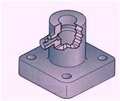
2. Which statement is true regarding the figure given below?
a) Full section view, where the section plane go completely through the object
b) Half section view, where the section plane go half-way through the object
c) Offset section, where the sectional plane bent through the features that are not aligned
d) Broken-out section where the section go through part of the object
View Answer
Explanation: A broken-out section view cuts away a portion of an assembly in a drawing view to expose the inside. Cross hatching is automatically generated on the sectioned faces of all components.
A broken-out section is part of an existing drawing view, not a separate view. A closed profile, usually a spline, defines the broken-out section. Material is removed to a specified depth to expose inner details. Specify the depth by setting a number or by selecting geometry in a drawing view.
You cannot create a broken-out section on a detail, section, or alternate position view. If you create a broken-out section of an exploded view, you cannot collapse the exploded view.
3. Which material property is shown by the 1st figure?
![]()
![]()
a) Tie and refractory materials
b) Earth
c) Rock
d) Thermal insulation
View Answer
Explanation: A refractory material is a material that retains its strength at high temperatures. ASTM C71 defines refractories as “…non-metallic materials having those chemical and physical properties that make them applicable for structures, or as components of systems, that are exposed to environments above 1,000 °F. Refractory materials are used in for furnaces, kilns, incinerators, and reactors. They are also used to make crucibles and moulds for casting glass and metals and for surfacing flame deflector systems for rocket launch structures. Today, the iron- and steel-industry uses approximately 70% of all refractories produced.
4. Which material property is shown by the 2nd figure?
![]()
![]()
a) Concrete
b) Earth
c) Electrical welding, electromagnets etc
d) Thermal insulation
View Answer
Explanation: Electric resistance welded (ERW) pipe is manufactured by cold-forming a sheet of steel into a cylindrical shape. Current is then passed between the two edges of the steel to heat the steel to a point at which the edges are forced together to form a bond without the use of welding filler material. Initially this manufacturing process used low frequency A.C. current to heat the edges. This low frequency process was used from the 1920s until 1970. In 1970, the low frequency process was superseded by a high frequency ERW process which produced a higher quality weld.
5. Which material property is shown by the 3rd figure?
![]()
![]()
a) Concrete
b) Earth
c) Sound insulation
d) Thermal insulation
View Answer
Explanation: Concrete is a composite material composed of coarse aggregate bonded together with a fluid cement that hardens over time. Most concretes used are lime-based concretes such as Portland cement concrete or concretes made with other hydraulic cements, such as ciment fondu. However, asphalt concrete, which is frequently used for road surfaces, is also a type of concrete, where the cement material is bitumen, and polymer concretes are sometimes used where the cementing material is a polymer.
6. Given below has four figure for section line, identify which one is correct?
a) 
b) 
c) 
d) 
View Answer
Explanation: The general purpose cast iron section line is drawn at a 45° and spaced 1.5 mm to 3 mm or more, depending on the size of the drawing. As a general rule, use 3mm spacing. Section lines are drawn as thin (.35 mm) black lines. The section lines should be evenly spaced and of equal thickness, and should be thinner than visible lines. Also, do not run section lines beyond the visible outlines or stop them too short.
7. Which figure is correct regarding the placement of dimensions or notes within the section lines?
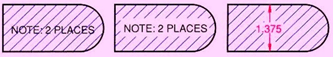
a) 1st
b) 2nd
c) 3rd
d) Both 2nd and 3rd
View Answer
Explanation: General Rules For Dimensioning are as follows:
- Dimensions should NOT be duplicated, or the same information be given in two different ways.
- No unnecessary dimensions should be used – only those needed to produce or inspect the part.
- Dimensions should be placed at finished surfaces or important center lines.
- Dimensions should be placed so that it is not necessary for the observer to calculate, scale, or assume any measurement.
- Dimensions should be attached to the view that best shows the shape of the feature to be dimensioned.
- Avoid dimensioning to hidden lines wherever possible.
- Dimensions should not be placed on the object unless that is the only clear option.
- Overall dimensions should be placed the greatest distance away from the object so that intermediate dimension can nest closer to the object to avoid crossing extension lines.
- A dimension should be attached to only one view (i.e., extension lines should not connect two views).
- Never cross dimension lines.
- Never cross extension lines.
- A center line may be extended and used as an extension line.
- Leaders should slope at a 30, 45 or 60 degree angle.
- Dimension numbers should be centered between arrowheads, except when using stacked dimensions then the numbers should be staggered.
- In general, a circle is dimensioned by its diameter, an arc by its radius.
- Holes should be located by their center lines.
- Holes should be located in the view that shows the feature as a circle.
- Extension lines start approximately 1/16″ from the object and extend 1/8″ past the last Dimension.
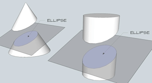
8. Figure below represents a section (shaded) obtained due to intersection by a plane that is parallel to the axes of the cones, what it the section called?
a) Parabola
b) Hyperbola
c) Ellipse
d) Cycloid
View Answer
Explanation: Hyperbola concept originated in Greek, can be defined as a set of points in a plane whose distances to two fixed points in the plane have a constant difference. It is formed by the intersection of a plane with a right circular cone. Equation of parabola: x2/a2 − y2/b2 = ±1.
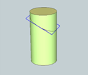
9. The Diagonal cross section of a cylinder obtained as shown in figure will be __________
a) circle
b) ellipse
c) hyperbola
d) spherical
View Answer
Explanation: The Diagonal cross section of a cylinder obtained as ellipse.
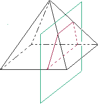
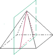
10. The cross-section perpendicular to the base but not through the vertex of a square pyramid will be a __________
a) square
b) triangle
c) trapezoid
d) rectangle
View Answer
Explanation: According to the question here (referring the figure), the green coloured line i.e. the plane, represents the axis away from the vertex through which the section is obtained. On cutting, the section obtained will be a trapezoid (shown by red dotted lines).
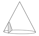
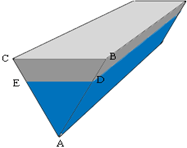
11. The cross-section perpendicular to the base of the shown figure is a__________
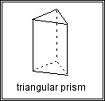
a) rectangle
b) square
c) triangle
d) trapezoid
View Answer
Explanation: Here in the figure below ED represents the perpendicular area in the triangular prism. On cutting across this area the section obtained will be rectangle type.
12. The cross-section through the vertex perpendicular to the base of the shown figure is a ___________
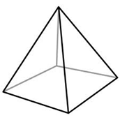
(SQUARE PYRAMID)
a) triangle
b) square
c) rectangle
d) trapezoid
View Answer
Explanation: According to the question here (referring the figure), the green coloured line i.e. the plane, represents the axis through which the section is obtained. On cutting, the section obtained will be a triangle (shown by red dotted lines).
Sanfoundry Global Education & Learning Series – Civil Engineering Drawing.
To practice all areas of Civil Engineering Drawing, here is complete set of 1000+ Multiple Choice Questions and Answers.
If you find a mistake in question / option / answer, kindly take a screenshot and email to [email protected]
- Check Civil Engineering Books
- Practice Civil Engineering MCQs
- Check Civil Engineering Drawing Books
- Apply for Civil Engineering Internship
