This set of Civil Engineering Drawing Multiple Choice Questions & Answers (MCQs) focuses on “Projections on Auxiliary Planes”.
1. The front and top view are sometimes not sufficient to convey all the information regarding the object. Additional views are therefore projected on other planes known as ____________
a) auxiliary vertical plane
b) auxiliary inclined plane
c) auxiliary plane
d) horizontal and Vertical plane
View Answer
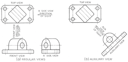
Explanation: Any view obtained by a projection on a plane other than the horizontal, frontal, and profile projection planes is an auxiliary view. A primary auxiliary view is projected onto a plane that is perpendicular to one of the principal planes of projection and is inclined to the other two. A secondary auxiliary view is projected from a primary auxiliary view onto a plane that is inclined to all three principal projection planes as shown in the figure below.
2. Auxiliary views cannot be used for the determining _____________
a) the true length of a line
b) the point-view of a line
c) the edge-view of a line
d) the apparent size
View Answer
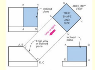
Explanation: The auxiliary views may also be used for determining – true length of a line, point-view of a line, edge- view of a line, true size and form of a plane etc as shown in the figure below.
3. Auxiliary planes are of _______ types.
a) two
b) one
c) three
d) six
View Answer
Explanation: These are A.V.P (Auxiliary vertical plane) and A.I.P. (Auxiliary inclined plane). Auxiliary vertical plane is perpendicular to the H.P. and inclined to the V.P. projection on an A.V.P. is called auxiliary front plane. Auxiliary inclined plane is perpendicular to the V.P. and inclined to the H.P. projection on an A.I.P. is called auxiliary top view.
4. What are non-parallel and non-intersecting lines called?
a) Spiral lines
b) Parallel lines
c) Skew lines
d) Perpendicular lines
View Answer
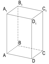
Explanation: A simple example of a pair of skew lines is the pair of lines through opposite edges of a regular tetrahedron. Two lines that both lie in the same plane must either cross each other or be parallel, so skew lines can exist only in three or more dimensions. Two lines are skew if and only if they are not coplanar. Referring the figure below, here the line through segment AD and the line through segment B1B are skew lines because they are not in the same plane.
5. The shortest distance between two parallel lines is equal to the length of the perpendicular drawn between them. If its true length is to be measured, then the two given parallel lines should be shown in their _________ views.
a) top
b) front
c) point
d) line
View Answer
Explanation: If the point views of the lines are required, then first they have to be shown in their true lengths in one of the orthographic views.
If none of the orthographic views show the given lines in their true lengths, an auxiliary plane parallel to the two given lines should be set up to project them in their true lengths on it.
Even the auxiliary view which shows the lines in their true lengths may not show the perpendicular distance between them in true length. Hence another auxiliary plane perpendicular to the two given lines should be set up. Then the lines appear as points on this auxiliary plane and the distance between these point views will be the shortest distance between them.
6. The end projectors of a line AB is 40 mm. The point A is 24 mm above HP and 10 mm in front of VP. Point B is 46 mm above HP and 46 mm in front of VP. What will be the True length of the line?
a) 57 mm
b) 37 mm
c) 50 mm
d) 47 mm
View Answer
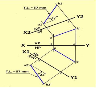
Explanation: Refer the figure below and the following steps-
• Draw the XY line. Draw two line perpendicular to XY line separated by a horizontal distance of 40 mm.
• Along the first line mark points a’ and a 24 mm above and 10 mm below XY line.
• Along the second line mark b and b’ 46 mm above and below XY line.
• Draw a reference line X1 Y1 parallel to line ab to represent the AVP.
• Through a and b, draw projectors to X1 Y1 line and extend it.
• Mark a2’ such that 3-a2’ = 5-a’. similarly mark b2’ such that 4-b2’ = 6b’.
• Join a2’-b2’ to obtain the true length of the line.
• The inclination of the line a2’-b2’ with X1Y1 line is the true inclination of the line with HP.
• Draw X2Y2 parallel to the front view a’b’ and project the auxiliary top view a1b1 in the similar manner. The inclination of the line a1-b1 with X2Y2 line is the true inclination of the line with VP.
By measurement, the following dimensions are obtained:
True length of the line is 57 mm.
7. Plane appears as foreshortened surface in all the projection planes is known as _________
a) The parallel plane
b) The vertical plane
c) The slant plane
d) The horizontal plane
View Answer
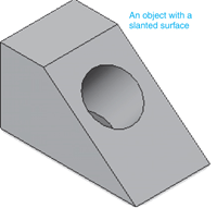
Explanation: A slant plane is defined as a plane that appears as a line in at least one of the standard views of projection (top, front), and foreshortened in the other views.
8. To save space on the drawing or to save time only ___________ view may be drawn.
a) Half auxiliary
b) Full auxiliary
c) Front
d) Top
View Answer
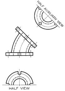
Explanation: If an auxiliary view is symmetrical, and if it is necessary to save space on the drawing or to save time, only half of the auxiliary view may be drawn, as shown below. In this case, half of a regular view is also shown since the bottom flange is also symmetrical as shown in the figure below.
9. Planes which are inclined to both the reference planes are called __________
a) vertical planes
b) inclined planes
c) horizontal planes
d) oblique planes
View Answer
Explanation: Oblique projection is a simple type of technical drawing of graphical projection used for producing two-dimensional images of three-dimensional objects. The objects are not in perspective, so they do not correspond to any view of an object that can be obtained in practice, but the technique does yield somewhat convincing and useful images. The plane at which these activity occur refers to as Oblique planes.
10. Auxiliary views tend to make use of ___________ projection.
a) orthographic projection
b) axonometric projection
c) oblique projection
d) isometric projection
View Answer
Explanation: Axonometric projection is a type of orthographic projection used for creating a pictorial drawing of an object, where the lines of sight are perpendicular to the plane of projection, and the object is rotated around one or more of its axes to reveal multiple sides.
11. In ____________ the direction of viewing is such that two of the three axes of space appear equally foreshortened.
a) orthographic projection
b) trimetric projection
c) dimetric projection
d) isometric projection
View Answer
Explanation: In dimetric projection, the direction of viewing is such that two of the three axes of space appear equally foreshortened, of which the attendant scale and angles of presentation are determined according to the angle of viewing; the scale of the third direction (vertical) is determined separately. Approximations are common in dimetric drawings.
12. In _________ the parallel projection rays are not perpendicular to the viewing plane as with orthographic projection, but strike the projection plane at an angle other than ninety degrees.
a) isometric projections
b) orthographic projections
c) axonometric projection
d) oblique projections
View Answer
Explanation: In both orthographic and oblique projection, parallel lines in space appear parallel on the projected image. Because of its simplicity, oblique projection is used exclusively for pictorial purposes rather than for formal, working drawings. In an oblique pictorial drawing, the displayed angles among the axes as well as the foreshortening factors (scale) are arbitrary. The distortion created thereby is usually attenuated by aligning one plane of the imaged object to be parallel with the plane of projection thereby creating a true shape, full-size image of the chosen plane.
Sanfoundry Global Education & Learning Series – Civil Engineering Drawing.
To practice all areas of Civil Engineering Drawing, here is complete set of 1000+ Multiple Choice Questions and Answers.
If you find a mistake in question / option / answer, kindly take a screenshot and email to [email protected]
- Practice Civil Engineering MCQs
- Check Civil Engineering Books
- Apply for Civil Engineering Internship
- Check Civil Engineering Drawing Books
