Transition graphs
Transition graph can be interpreted as a flowchart for an algorithm recognizing a language. A transition graph consists of three things:
- A finite set of states, at least one of which is designated the start state and some of which are designated as final states.
- An alphabet Σ of possible input symbols from which the input strings are formed.
- A finite set of transitions that show the change of state from the given state on a given input.
A successful path through the transition graph is a series of edges forming a path beginning at the start state and ending at one of the final states.
Some of the transition graphs are given below

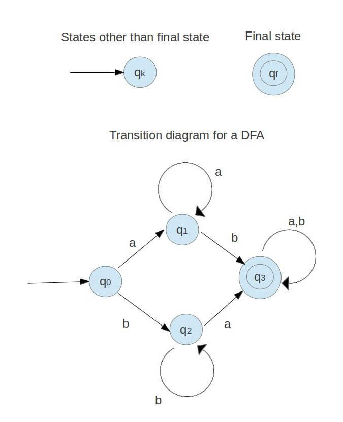
The transition graph in the figure represents a DFA with at least one a and at least one b.
A transition diagram for DFA, M = ( Q, Σ, δ, F, q0) is a graph defined as follows:
(a) For each state in Q there is a node represented by the circle.
(b) For each state q in Q each input symbol a in Σ, let δ(q, a) = q’. Then transition diagram has an arc from q to q’, labelled a.
(c) There is always an arrow into the start state that is not from any other state.
(d) Nodes corresponding to accepting states are denoted by a double circle. Rest of the states are depicted by a single circle.
Transition tables
A transition table is a tabular representation of the transition function that takes two arguments and returns a state. The column contains the state in which the automaton will be on the input represented by that column. The row corresponds to the state the finite control unit can be in. The entry for one row corresponding to state q and the column corresponds to input a is the state δ(q, a).
For the transition graph in the above figure the transition table would be as follows:
| states | a | b |
|---|---|---|
| q0 | q1 | q2 |
| q1 | q1 | q3 |
| q2 | q2 | q3 |
| *q3 | q3 | q3 |
In the above table we observe that on giving a as input to DFA in state q0 the DFA changes state to q1 and on input b the state changes to q2. Similarly by writing this information for other states we generate the transition graph.
Sanfoundry Global Education & Learning Series – 100+ Theory of Computation Tutorials.
If you wish to look at all Tutorials and their examples, go to Theory of Computation Tutorials.
- Check Computer Science Books
- Practice Computer Science MCQs
- Check Automata Theory Books
- Apply for Computer Science Internship
