This set of Arduino Multiple Choice Questions & Answers (MCQs) focuses on “Setting Pin Mode”.
1. What type of signal does the analogWrite() method generate when a pin is set to OUTPUT mode?
a) Digital Signal
b) Pulse Code Modulated Signal
c) Pulse amplitude Modulated Signal
d) Pulse Width Modulated Signal
View Answer
Explanation: The analogWrite() method in Arduino is used to generate a Pulse Width Modulated Signal since the digital circuitry in the Arduino does not allow for generation of true continuous analog waves. So therefore, the PWM Signal is used.
2. What is the output of “pin1” if “pin2” is sent “1011” where 1 is 5V and 0 is 0V?
int pin1 = 12;
int pin2 = 11;
void setup() {pinMode(pin1, OUTPUT);
pinMode(pin2, INPUT);
Serial.begin(9600);
}
void loop() {if(digitalRead(pin2)==1) {digitalWrite(pin1,LOW);
}
else if(digitalRead(pin2)==0) {digitalWrite(pin1,HIGH);
}
}
a) 0100
b) 1011
c) 1110
d) 1111
View Answer
Explanation: Here when pin2 receives a digital 1 we set pin1 as “LOW” or a digital 0, and conversely when pin2 receives a digital 0 we set pin1 as “HIGH” or a digital 1. Therefore, effectively generating the inverse of the wave that we received as input.
3. What are the two modes that the pinMode() method sets for a particular pin?
a) DIGITAL and ANALOG
b) INPUT and OUTPUT
c) TX and RX
d) READ and WRITE
View Answer
Explanation: The pinMode() method determines whether the pin number given in the code is to be used as an input pin wherein it can read voltage from an external circuit or for setting a particular voltage at the pin output to be plugged to an external circuit.
4. What are the voltage levels that can be detected if a pin is set to OUTPUT using the pinMode() method and the analogRead() method is used, in the Arduino Uno?
a) 0 and 5V
b) 0 to 5.1V
c) 0 to 5V
d) 0 to 10V
View Answer
Explanation: The Arduino UNO has an operating voltage ranging from 0V to 5V. Hence the Serial monitor will record an output ranging from 0 to 1023. This is done by mapping the value of the voltage to an integer set that has a range of 0 to 1023.
5. What will the code given below give as output if a 5V line is connected as input to pin 11?
int pin_1=11;
void setup() {pinMode(pin_1, INPUT);
Serial.begin(9600);
}
void loop() {int reading=analogRead(pin_1);
Serial.println(reading);
}
a) 0
b) 102
c) Null
d) 1023
View Answer
Explanation: The voltage that is put across the pin 11 goes into the analog to digital convertor onboard the Arduino and then it is converted into an integer value that ranges from 0 to 1023. This is done by “mapping” the voltage value read, to a range of integers from 0 to 1023.
6. What is the output at the serial monitor of the code below if pin 11 is given the following signal?
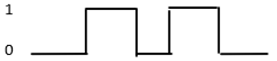
int pin1=11;
void setup() {pinMode(pin1, INPUT);
Serial.begin(9600);
}
void loop() {int ip=analogRead(pin1);
if(ip>0) {Serial.println(“H”);
}
else {Serial.println(“O”);
}
}
a) 0H0H0
b) OHHO
c) OHHH
d) HOHOO
View Answer
Explanation: The input signal given is of the form 01010. Therefore, according to the code, if ip is greater than 0 then ‘H’ is printed and if ip is less than 0 then ‘O’ is printed. So now we get the output as OHOHO. This is printed to the Serial Monitor with a baud rate of 9600.
7. How many errors are present in the code given below?
int pin1=12;
void setup() {pinmode(pin1, IN);
Serial.begin(9600);
}
void loop() {int value=analogRead(pin1);
Serial.println(value+10);
}
a) 1
b) 2
c) 3
d) 4
View Answer
Explanation: There are 2 errors in the code given below. They are present in line 4. In line 4 the syntax of the “pinMode()” function is wrong since the ‘M’ is not a capital letter, and while setting pin1 as an input port, we have to write the second argument of the function as “INPUT” not “IN.
8. What is the output of the program given below if a 0V is put across pin 11?
int pin=11;
void setup() {pinMode(pin, INPUT_PULLUP);
Serial.begin(9600);
}
void loop() {int a=digitalRead(pin);
Serial.println(a);
}
a) 1
b) 0
c) 0.3
d) 1.001
View Answer
Explanation: The reading across the pin would be given as 1 (digital HIGH) since the pinMode is set to INPUT_PULLUP which basically pulls the reading up to the maximum when there is no voltage applied across the pin, but functions as a normal input pin for reading voltage levels when some amount of voltage is applied across it.
9. What is the difference between the INPUT and INPUT_PULLUP arguments in the pinMode() function?
a) They are both the same
b) INPUT supports only analog voltages while INPUT_PULLUP supports only digital voltage readings
c) INPUT takes the default reading as 0 while INPUT_PULLUP takes default reading as 1023
d) INPUT takes the default reading as 1023 while INPUT_PULLUP takes the default reading as 0
View Answer
Explanation: The pinMode() function has 2 arguments; the pin number and the mode. The pin number argument takes the number of the pin as input while the mode can be set in 3 different ways, including INPUT, OUTPUT, and INPUT_PULLUP. Here the OUTPUT argument makes the pin ready for sending signals, the INPUT argument makes the pin take a voltage as input from an external source. The INPUT_PULLUP also does the same function as INPUT however only differing in the aspect of base voltage, where the INPUT argument pulls down the voltage of that port to 0V every time there is no voltage is detected across the port while the INPUT_PULLUP argument pulls up the voltage across the port to the maximum for that board whenever there is no input voltage across the port, and the reading at the port decreases with increase in voltage applied across the port.
10. What is the purpose of the code given below?
int pin=11;
void setup() {pinMode(pin, INPUT);
Serial.begin(9600);
}
void loop() {int a=1023-analogRead(pin);
Serial.println(a);
}
a) To demonstrate the working of the INPUT_PULLUP argument
b) To emulate the working of the OUTPUT argument
c) To emulate the analogRead method
d) To reset all input to 0
View Answer
Explanation: The code given above inverts whatever voltage reading we get from the pin by subtracting the value that is acquired from the analogRead() method, from 1023, which corresponds to the maximum voltage that can be detected at the port.
Sanfoundry Global Education & Learning Series – Arduino.
To practice all areas of Arduino, here is complete set of 1000+ Multiple Choice Questions and Answers.
If you find a mistake in question / option / answer, kindly take a screenshot and email to [email protected]
- Check Electrical Engineering Books
- Check Arduino Books
- Apply for Electrical Engineering Internship
- Practice Electrical Engineering MCQs
- Check Electrical & Electronics Engineering Books
