This set of Power Electronics Multiple Choice Questions & Answers (MCQs) focuses on “Firing Circuits-1”.
1. In a single pulse semi-converter using two SCRs, the triggering circuit must produce
a) two firing pulses in each half cycle
b) one firing pulse in each half cycle
c) three firing pulses in each cycle
d) one firing pulse in each cycle
View Answer
Explanation: A single phase semi-converter has only two SCRs & two diodes. Hence, only two pulses are required in each cycle, one in each half.
2. In a 3-phase full converter using six SCRs, gating circuit must provide
a) one firing pulse every 30°
b) one firing pulse every 90°
c) one firing pulse every 60°
d) three firing pulses per cycle
View Answer
Explanation: 60° x 6(devices) = 360°.
3. In the complete firing circuit, the driver circuit consists of
a) pulse generator & power supply
b) gate leads & power supply
c) pulse amplifier & pulse transformer
d) pulse detector & pulse amplifier
View Answer
Explanation: The driver circuit consists of a pulse amplifier to increase the magnitude of the gate pulse to a sufficient value. The pulse transformer then provides pulses to individual SCRs.
4. Find the average gate power dissipation (Pgav) when the maximum allowable gate power dissipation (Pgm) = 10 kW, with a duty cycle = 50 %.
a) 10 KW
b) 5 KW
c) 2.5 KW
d) 7 KW
View Answer
Explanation: (Pgm) = (Pgav)/Duty Cycle.
5. The magnitude of gate voltage and gate current for triggering an SCR is
a) inversely proportional to the temperature
b) directly proportional to the temperature
c) inversely proportional to the anode current requirement
d) directly proportional to the anode current requirement
View Answer
Explanation: Higher the temperature lesser will be the gate current required as the temperature must have already excited some of the atoms.
6. Find the amplitude of the gate current pulse, when the gate-cathode curve is given by the relation Vg = [(1+10) x Ig]
The peak gate drive power is 5 Watts.
a) 359mA
b) 659mA
c) 1.359 A
d) 1.659 A
View Answer
Explanation:
(1+10 Ig).Ig = 5 Watts
Ig = 0.59 A.
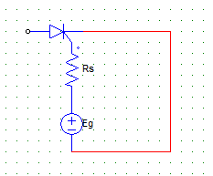
7. The gate-cathode curve for an SCR is given by the relation Vg = (1+10)Ig. The gate voltage source is a rectangular pulse of peak value 15 V and current = 0.659 A. Find the source resistance.
a) 90.2 Ω
b) 11.24 Ω
c) 46.2 Ω
d) 39 Ω
View Answer
Explanation: Es = Rs.Ig + Vg
Vg = 1+10 Ig
Therefore Rs = (15-1)/0.659.
8. Find the triggering frequency when the average gate power dissipation = 0.3 W and the peak gate drive power is 5 Watts. The gate source has a pulse width of 20 μsec duration.
a) 3 kHz
b) 0.3 kHz
c) 30 kHz
d) 0.03 mHz
View Answer
Explanation: (Pgm) = (Pgav)/Duty Cycle
Duty Cycle = f x T = (Pgav)/(Pgm)
Duty Cycle = 0.3/5
T = 20 μsec.
0.3/5 = f x T
f = (0.3)/(5 x 20 x 10-6) = 3000 Hz.
9. The duty cycle can be written as
a) f x T
b) f/T
c) T/f
d) f
View Answer
Explanation: The duty cycle is defined as the ratio of pulse-on period to periodic time of pulse.
The pulse on period is T, and the periodic time is 1/f.
It is to be noted that T = pulse width whereas f = (1/T1) = frequency of firing or pulse repetition rate.
10. The major function of the pulse transformer is to
a) increase the voltage amplitude
b) reduce harmonics
c) isolate low & high power circuit
d) create periodic pulses
View Answer
Explanation: Isolation of the two circuit is done by the transformer, as the transformer is a magnetically coupled device and any mishap at the load side will not damage the other side of the circuitry.
Sanfoundry Global Education & Learning Series – Power Electronics.
To practice all areas of Power Electronics, here is complete set of 1000+ Multiple Choice Questions and Answers.
If you find a mistake in question / option / answer, kindly take a screenshot and email to [email protected]
