This set of Power Electronics Multiple Choice Questions & Answers (MCQs) focuses on “Three-Phase Rectifiers-2”.
1. A step-down delta-star transformer, with per-phase turns ratio of 5 is fed from a 3-phase 1100 V, 50 Hz source. The secondary of this transformer is connected through a 3-pulse type rectifier, which is feeding feeding an R load. Find the average value of output voltage.
a) 220 V
b) 257 V
c) 1100/√3 V
d) 206 V
View Answer
Explanation:
Vph = 1100/5 = 220 V (Transformer ratio = 5)
Vmp = √2 x 220 V
Vo = 3√3/2π x Vmp = (√2 x √3 x 3 x 220)/(2 x π).
2. The circuit shown below is that of a
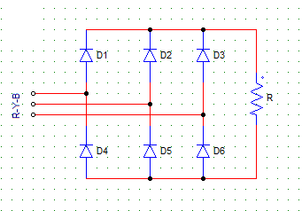
a) 3-phase, 6-pulse, diode rectifier
b) 3-phase, 6-pulse, diode inverter
c) 3-phase, 3-pulse, diode rectifier
d) 3-phase, 3-pulse, diode inverter
View Answer
Explanation: A 3-phase, 6-pulse rectifier consists of 6 diodes connected in 3 legs. Two diodes conduct at a time.
3. A step-down delta-star transformer, with per-phase turns ratio of 5 is fed from a 3-phase 1100 V source. The secondary of this transformer is connected through a 3-pulse type rectifier, which is feeding an R load.
The power delivered to the load is 6839.3 Watts.
The maximum value of the load current is √2 x 22 A.
Fin, the rms value of output voltage Vo (rms)
a) 257.3 V
b) 220 V
c) 261.52 V
d) 248.32 V
View Answer
Explanation: Power delivered to the load (Pdc) = Vo(rms)2/R (i)
Imp = Vmp/R
Therefore, R = Vmp/Imp = (1100 x √2)/(5 x √2 x 22) = 10 Ω
Put R in equation (i) & find the required R.M.S voltage.
4. From the diode rectifier circuit shown below, with phase sequence R-Y-B, diodes D3 & D5 conduct when
a) R is the most positive & B is the most negative
b) R is the most positive & Y is the most negative
c) R is the most negative & B is the most positive
d) R is the most negative & Y is the most positive
View Answer
Explanation: Which diode will conduct depends on where is it in connected? as in in which phase?. D3’s anode is connected to the R phase, hence it will turn on when R is the most positive.
5. From the diode rectifier circuit shown below, with phase sequence R-Y-B, from ωt = 150° to 270°
a) D1
b) D2
c) D3
d) None of the diodes conduct
View Answer
Explanation: Construct the phase voltage waveforms on a graph. At 150 degree, D2 is forward biased while the other positive group diodes i.e. D2 and D3 remain reserved biased.
6. A 3-phase 6-pulse diode rectifier is shown below with phase sequence R-Y-B. The negative group of diodes (D4, D5, D6) conduct in sequence (from ωt = 0°)
a) D4-D5-D6
b) D5-D6-D4
c) D6-D5-D4
d) D6-D4-D5
View Answer
Explanation: The conduction sequence always depends on the phase sequence, which diode is conducting will depend upon which phase voltage is active at that moment.
7. For a 3-phase 6-pulse diode rectifier, has Vml as the maximum line voltage value on R load. The peak current through each diode is
a) Vml/2R
b) 2Vml/R
c) Vml/R
d) Insufficient Data
View Answer
Explanation: Two diodes conduct at a time, constructing the equivalent circuit with supply, R & replacing the conducting diodes by S.C & non-conducting as O.C, the required value can be found out.
8. A 3-phase bridge rectifier, has the average output voltage as 286.48 V. Find the maximum value of line voltage
a) 100 V
b) 200 V
c) 300 V
d) 400 V
View Answer
Explanation: Vo = 3Vml/π
Vml = (π x Vo)/3 = 300 V.
9. A 3-phase bridge rectifier charges a 240 V battery. The rectifier is given a 3-phase, 230 V supply. The current limiting resistance in series with the battery is of 8 Ω.
Find the average value of battery charging current.
a) 12.56 A
b) 8.82 A
c) 9.69 A
d) 6.54 A
View Answer
Explanation: Vo = (3√2 x 230)/π = 310.56 V
Draw the battery charging circuit,
Vo = E + (Io x R)
Io = (Vo – E)/R = (310.56 – 240)/8.
10. A 3-phase bridge rectifier charges a 240-V battery. The rectifier is given a 3-phase 230 V supply. The current limiting resistance in series with the battery is 8 Ω.
Find the power delivered to the battery (Pdc).
a) Pdc = 2000 W
b) Pdc = 1226 W
c) Pdc = 2356 W
d) Pdc = 2116 W
View Answer
Explanation: Vo = (3√2 x 230)/π = 310.56 V
Draw the battery charging circuit,
Vo = E + (Io x R)
Io = (Vo – E)/R = (310.56 – 240)/8 = 8.82A
Pdc = 240 x 8.82 = 2116 W.
Sanfoundry Global Education & Learning Series – Power Electronics.
To practice all areas of Power Electronics, here is complete set of 1000+ Multiple Choice Questions and Answers.
If you find a mistake in question / option / answer, kindly take a screenshot and email to [email protected]
