This set of Power Electronics Multiple Choice Questions & Answers (MCQs) focuses on “1-Phase-Diode Rectifiers FW-2”.
1. The PIV experienced by each of the diodes for the below shown rectifier configuration is
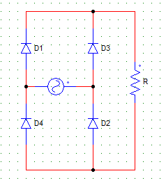
a) Vm
b) 2Vm
c) 3Vm
d) Vm/2
View Answer
Explanation: When any diode is reversed biased due to the negative half cycle, the maximum peak value through it will be Vm.
2. For the circuit shown in the figure below,
Vs = 230 V
R = 10Ω
Find the average value of output current.
a) 207.04 A
b) 20.704 A
c) 2.0704 A
d) 207.04 mA
View Answer
Explanation: I = Vo/R
Vo = 2Vm/π.
3. Choose the correct statement regarding the below given circuit.
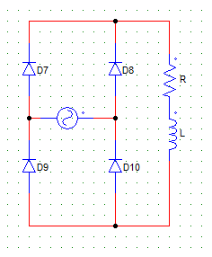
a) The load current is never negative
b) The load current is never zero
c) The load current is never positive
d) The load voltage is never negative
View Answer
Explanation: Due to the inductive nature of the load, the Diodes are force conducted & voltage goes negative but the current can never fall below zero.
4. For a single phase, full bridge, diode rectifier excited from a 230 V, 50 Hz source. With R = 10 Ω & the inductance(L) large enough to maintain continues conduction, the average and rms values of diode currents will be
a) 7.85 A, 8 A
b) 10.35 A, 7.85 A
c) 10.35 A, 14.6 A
d) 8 A, 8 A
View Answer
Explanation:
Id(avg) = Io/2 = Vo/2R
Id(rms) = Io/√2 = Vo/R√2.
5. The circuit shown below, will have the output voltage waveform similar to that of a
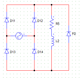
a) half wave rectifier with RL load
b) full wave bridge rectifier with RL load
c) full wave bridge rectifier with R load
d) full wave bridge rectifier with RC load
View Answer
Explanation: The FD short circuits the load & voltage waveform is similar to that of a Full wave bridge rectifier with R load.
6. For the circuit shown below, the load current attains the maximum value at ωt =
a) 0
b) π
c) 2π
d) none of the mentioned
View Answer
Explanation: As the load is RL, the load current will be maximum when the output voltage waveform falls to zero i.e. at π. At π the inductor is charged to its maximum value and starts delivering power to the source.
7. For a single phase, full bridge, diode rectifier excited from a 230 V, 50 Hz source. With R = 10 Ω & the inductance(L) large enough to maintain continuous conduction, the value of the supply power factor will be
a) 0.707 lag
b) 0.9 lag
c) 0.86 lag
d) Unity
View Answer
Explanation:
Pf = Vs.Is.cosθ/Vo.Io
Io = Vo/R A
Vo = 2Vm/π Volts.
8. The rectification efficiency for B-2 type & M-2 type full wave diode rectifiers are ___ & ___ respectively.
a) 8/π & 4/π
b) 4/π & 8/π
c) 8/π & 8/π
d) 4/π & 4/π
View Answer
Explanation: B-2 type has efficiency 8/π. M-2 type has efficiency half of that of a B-2 type.
9. A load of R = 60 Ω is fed from 1phase, 230 V, 50 Hz supply through a step-up transformer & than a diode. The transformer turns ratio = 2. The power delivered to the load is
a) 614 Watts
b) 714 Watts
c) 814 Watts
d) 914 Watts
View Answer
Explanation: P = Vo2/R
Vo = Vm/π
AC supplied to the rectifier is 2 x 230 = 460 V (rms)
Therefore, Vo = √2 x 460 / π = 207.04
P = 714.43 W.
10. For the circuit shown below, D11 & D14 conduct from?
Assume that anode of D12 is positive at ωt = 0 and likewise.
a) 0 to π
b) π to 2π
c) 2π to 3π
d) 0 to π/2
View Answer
Explanation: In the first cycle i.e. 0 to π, D12 and D13 conduct. In the next cycle i.e. π to 2π, D11 and D14 conduct.
Sanfoundry Global Education & Learning Series – Power Electronics.
To practice all areas of Power Electronics, here is complete set of 1000+ Multiple Choice Questions and Answers.
If you find a mistake in question / option / answer, kindly take a screenshot and email to [email protected]
