This is a PLC Program to Store Data of Various Process Sequentially.
Problem Description
There are total two parameters to be monitored of a tank. Display level and temperature of this tank for 5secs each. Implement this in PLC using Ladder Diagram programming language.
Problem Solution
- Continuous measurement is necessary in this case.
- Continuous level measuring devices such as Ultrasonic or Pressure level sensor can be used and for temperature, RTD or Thermocouple can be used.
- Output of these sensors are in analog form, so to deal with such analog data, analog modules are used in PLC.
- Analog modules convert analog signal into equivalent hex form.
- Convert this into Temperature in degree centigrade and level in height in cm.
- Generate time base to MOV output storing register value to display address after converting into BCD equivalent.
- Use either number of timers or Sequential Output instruction to solve this problem.
PLC Program
Here is PLC program to Store Data of Various Process Sequentially, along with program explanation and run time test cases.
List of Inputs and Outputs
 I:1		= Level Input from Tank 			(Input)
 I:2		= Temperature Input from of the Tank		(Input)
 N7:0 and N7:1	= Store and  process data of tank level		(Register)
 N7:2 and N7:3	= Store and process data of tank Temperature	(Register)
 T4:0, T4:1	= Timers to switch display data every 5secs	(Timers)
Ladder diagram showing conversion of inputs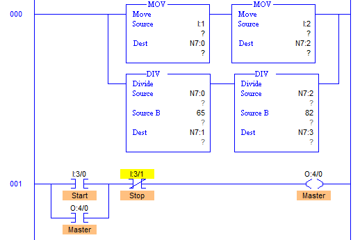
Ladder diagram to display level and temperature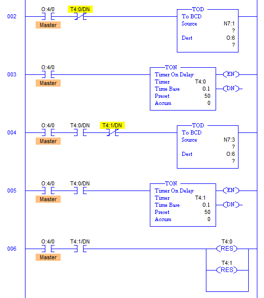
Program Description
- When level in tank rises, output of sensor increases accordingly.
- Suppose we have a tank with height 1000cm.
- Converting 16bit data into 1000cm height, 65 is the answer which means, increment of 65 is obtained per centimeter rise in tank level.
- Input data from I:1 is continuously moved to N7:0 which means data in N7:0 register continuously varies.
- Value stored in N7:0 is divided by 65 and stored in register N7:1.
- Value stored in N7:1 register is first converted into equivalent BCD number before feeding it to display which is connected with output module at address O:6.
- Similarly output of temperature is processed.
- Temperature range is 800 (-150 to 650 degree centigrade), hence when input is divided by 82, output is in temperature in degree centigrade.
- Work of timers here is just to change the input register address from which data is to be moved to output display every 5secs.
- After completion of each cycle, timers are reset by RUNG006.
- It just shows two process of a tank, more processes can be displayed similarly.
Runtime Test Cases
Inputs	        Outputs 	Physical Elements
O:2/0 = 1	O:6 = N7:1	Display level of the Tank
T4:0/DN = 1	O:6 = N7:3	Display temperature of the Tank
T4:1/DN = 1	O:6 = N7:1	Switch back to displaying level of the Tank
Sanfoundry Global Education & Learning Series – PLC Algorithms.
To practice all PLC programs, here is complete set of 100+ PLC Problems and Solutions.
advertisement
advertisement
